mNo edit summary |
|||
| (5 intermediate revisions by the same user not shown) | |||
| Line 23: | Line 23: | ||
* 2x gate in | * 2x gate in | ||
* 2x gate out | * 2x gate out | ||
* <s>based on</s>inspired | * <s>based on</s>inspired by https://micro-twin.com/hardware.php | ||
==== Second version ==== | ==== Second version ==== | ||
bugfixes | |||
* CV-out range fix (caused by parallel resistors) | |||
==== xth version ==== | |||
* more analogue in, 12 bit resolution by using a [http://ww1.microchip.com/downloads/en/devicedoc/21298e.pdf MCP3204 or MCP3208] or so? | * more analogue in, 12 bit resolution by using a [http://ww1.microchip.com/downloads/en/devicedoc/21298e.pdf MCP3204 or MCP3208] or so? | ||
| Line 48: | Line 53: | ||
=== to do === | === to do === | ||
* | * | ||
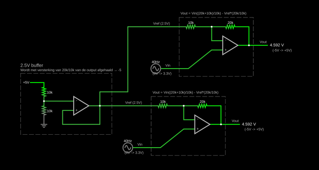
=== 0...3.3V to -5/+5V === | === 0...3.3V to -5/+5V === | ||
[https://www.falstad.com/circuit/circuitjs.html?ctz= | [https://www.falstad.com/circuit/circuitjs.html?ctz=CQAgjCAMB0l3BWcZYA4BsB2ATNzZsEBOVA9EBSCiqhAUwFowwAoAQxAGZUAWEI8ggL9yqcFSZUw8eF2hgimHp0ioEuPDzCZMchUsxYl6dYqLiZLAPIVhAkOlUjwUdiAadsXL-c8gxSAxI0jJU2NBI4ZRwhPCxMeQh8CwA7u5+PGIePuSQqek5zvZ5afZl5H55AE7u9mDkDPaoVFKWNY0NmbWJuRZwLABK3e5dTI4jYi0gPLRQczAILADmw83Dxa5p2eANdbn5KnzaFbzIXtUghBVenOhilX0X3Hx+Qjfnl5Zpt-c3p5UHU5rZ7eTa2d7g5wlZx+K6gvIAD3c2l0DFQunq5jRfCOXgA6gB7KoAEwALgAdADOAFs6BTKQA3OhVSmk5kAawAlgA7JZUhlsblU7CQdkAemk7P5gqpxLoVIJAFdSQAHZVUtgAMyWdAAFmw2AAbYlUwBJhFSgiwkWBSOBFJceOQRVRcSAABSQABqFoAfFTONBOJ6AJRWihETjIXQmcwEF3gLxuoLeykMP2U8kqhAhlgAI2RhncazAnAxnAgeXzeA+6l0IsjiILqOkXkkEiI5iOToiKdzis1muZYbwzdokEjDF0rs9Svp5IAjlTPTy3W6RVKVZLgxLRcGLUuqnRNQAqNeinfs0PW1CRwgOsJiaeHzVUtc9q+XO+Yh1ebReac8mGCA8OYqABJgkZEBA06zoMXCQEchYKL+hZSNMUjQCY4CYUgLQRHBMztk6YHDGhMzYVhKBYXhixIugPCBDafDoOgWI2tBCYgDOyphp4ECSJGnDcMicDTJxy7csOmBYtgPC6EJDSyTi4nPq+UQ5kipYTtgqBeMQMnSWJwjcXOi6UhJq7rpmW4XnuqYHkep7rrZeZcHc7jVg42ATqxrh0agbEIEgmBBci6hGYmya+lSmbZh+I7uCFXA8K2OARe6XrRZSAZBqGaTIR55GcOFDCyS0+SOFkZUOE4TCofkmQSAVjWFeVaSOnwpXkS1XXlTUPXVZVrVzM6-Q1MVrbVR1w2tMk7WiR00xrGM5U2ENdXkJgCEFokrgcD1xw1Vkh1iNIImPKJAb6MoqjqLgSjaIJ8iKHJRiOqYmAYBd+QFb1dqtvUYK-YD9hjGCoMg9crgEi49FzDMJDiFA8hzKwQA falstad circuitjs simulation] | ||
The opamp needs +12 and -12 for power. | |||
Schematic thanks to Kartoffel. | |||
[[File:Circuit-20220715-2051.png|640px]] | [[File:Circuit-20220715-2051.png|640px]] | ||
| Line 79: | Line 79: | ||
* gate signals can be toggled via e.g. wiringpi | * gate signals can be toggled via e.g. wiringpi | ||
=== history === | |||
* 28/7/2022: ordered a few test-pcbs at jlcpcb | |||
* 5/8/2022: problem in op-amp circuit for cv-out (output range incorrect due to resistor sharing in bias input) | |||
Latest revision as of 08:28, 6 August 2022
| Eurocrack-hat | |
|---|---|
| Participants | |
| Skills | Electronics, Programming |
| Status | Active |
| Niche | Music |
| Purpose | Fun |
| Tool | No |
| Location | |
| Cost | |
| Tool category | Electronics,Eurorack |
Nurd-euro-pi.jpg {{#if:No | [[Tool Owner::{{{ProjectParticipants}}} | }} {{#if:No | [[Tool Cost::{{{Cost}}} | }}
specifications
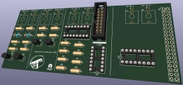
This will be an interface between eurorack signals ("control voltage" and "gates", all in the Doepfer range of -5V...+5V) and a raspberry pi (a "hat"). For that, the hat will have an ADC and a DAC (multichannel) connected via SPI (multichannel and not multiple devices as the rpi has only 2 SPI channels).
First version
- 2x analogue in (10 bit resolution, MCP3008, 0.5mA max power consumption)
- using https://github.com/scottellis/mcp3008-speedtest I saw sample-speeds of 13k upto 36k samples per second (on a raspberry pi 2) by tweaking the block-size and the bus-speed (of course)
- 2x analogue out (12 bit resolution, MCP4922, 0.7mA max power consumption )
- 2x gate in
- 2x gate out
based oninspired by https://micro-twin.com/hardware.php
Second version
bugfixes
- CV-out range fix (caused by parallel resistors)
xth version
- more analogue in, 12 bit resolution by using a MCP3204 or MCP3208 or so?
- more analogue out, gates in
- LEDs for gate status
- pins for neopixel connection (gnd + signal)
- I2C breakout (for e.g. small displays)
- SPI extender? (does something like that exist?)
- SMD technology maybe?
schematics
- Kicad files: see github
- PDF of revision 001: File:Nurd-euro-pi-001.pdf
component selection
to do
0...3.3V to -5/+5V
The opamp needs +12 and -12 for power.
Schematic thanks to Kartoffel.
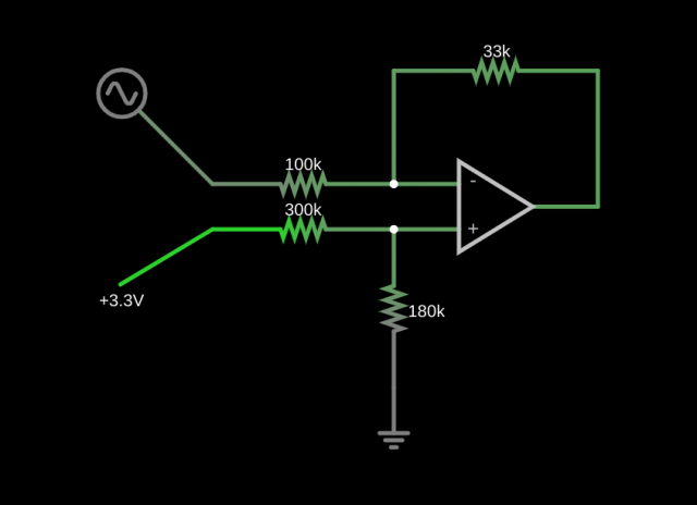
-5/+5V to 0...3.3V
The opamp needs +3.3V and 0V for power.
software
- I've chosen a DAC and ADC with SPI to easily connect them to a raspberry pi.
- gate signals can be toggled via e.g. wiringpi
history
- 28/7/2022: ordered a few test-pcbs at jlcpcb
- 5/8/2022: problem in op-amp circuit for cv-out (output range incorrect due to resistor sharing in bias input)


