| NURDspace Project | |
|---|---|
| Participants | |
| Skills | |
| Status | |
| Niche | |
| Purpose | |
| Tool | |
| Location | |
| Cost | |
| Tool category | |
{{{Name}}}Property "Tool Name" (as page type) with input value "{{{Name}}}" contains invalid characters or is incomplete and therefore can cause unexpected results during a query or annotation process. Property "Tool Image" (as page type) with input value "File:{{{Picture}}}" contains invalid characters or is incomplete and therefore can cause unexpected results during a query or annotation process. {{{Picture}}} {{#if:{{{Tool}}} | [[Tool Owner::SmokeyD | }} {{#if:{{{Tool}}} | [[Tool Cost::{{{Cost}}} | }}
I am building a Radio Spectrum Analyzer which measures signal strenght in the 2.4GHz band, using a CYWM6935 module and Atmega 328 MCU. I want to set it up in several steps:
Atmega328 on a breadboard
There are quite a few good "Arduino on a breadboard" tutorials out there. I suggest you take a look at
These were the components I bought (or borrowerd here on the nurdpspace):
- Atmega328 MCU with Arduinno bootloader
- 3x 2.2 KOhm resistor
- 3x 1 KOhm resistor
- 1x 10 KOhm resistor
- 1x reset switch
- 1x red LED
- 4x jumpers
- 18pF ceramic disc capacitors
- 16MHz crystal oscillator
- CYWM6935 wireless USB radio module
- Any breadboard. I bought a small one since I thought I would have plenty of space, but I was mistaken, and would recommend a large one. The larger the better really.
- FTDI cable
- A plate full of spaghetti. Aka: solid core red wire
- A few cases of beer
- A few pizzas
Connecting the CYWM6935
Programming the Atmega328
Creating desktop software for visualization
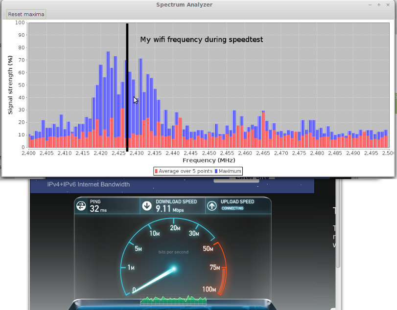
I chose to create a Java GUI using JFreeChart to read the data from the Arduino using an FTDI cable on a serial port (or actually USB) and visualize that in the GUI. The program can be found on Github.
This is a screenshot from the app. It allows you to reset the maxima by clicking the button.

