No edit summary |
|||
| Line 12: | Line 12: | ||
== Hardware == | == Hardware == | ||
The model number is AM03127. | |||
It has 16 elements of 5x8 LEDs each, for a total of 80x7 LEDs. | It has 16 elements of 5x8 LEDs each, for a total of 80x7 LEDs. | ||
Revision as of 18:42, 26 March 2022
| LED ticker | |
|---|---|
| Participants | |
| Skills | |
| Status | Active |
| Niche | |
| Purpose | Information viewer |
| Tool | No |
| Location | space |
| Cost | |
| Tool category | |
LED ticker Property "Tool Image" (as page type) with input value "File:" contains invalid characters or is incomplete and therefore can cause unexpected results during a query or annotation process.
{{#if:No | [[Tool Owner::{{{ProjectParticipants}}} | }} {{#if:No | [[Tool Cost::{{{Cost}}} | }}
This page is about a lichtkrant, brought by flok.
Hardware
The model number is AM03127.
It has 16 elements of 5x8 LEDs each, for a total of 80x7 LEDs. This particular board has monochrome LEDs only.
The electronics consist of two boards: a controller board and a LED board.
The LED board has the following ICs:
- SN74HC138: 3-to-8 line decoder/multiplexer
- SN74HC04: 6 inverters
- 10x SN74HC164: 8-bit parallel-out serial shift registers
- 4x APM4953: dual P-Channel Enhancement Mode Mosfet
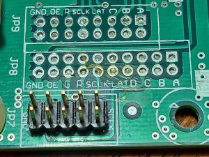
The boards are connected through a 10 pin connector and a 5V power connector.
Control connector
Pinout:
- pin 1: SCLK
- pin 2: SCLK (shorted to pin 1)
- pin 3: G = 'green' data bit shifted into row, goes through inverter 6
- pin 4: R = 'red' data bit, goes through inverter 1
- pin 5: A = row select
- pin 6: B = row select
- pin 7: C = row select
- pin 8: D = not clear what this is, perhaps this is just another bit for the row selector, not actually used for this particular board
- pin 9: GND
- pin 10: GND
| SCLK | SCLK |
| R | G |
| B | A |
| D | C |
| GND | GND |
Unfortunately the connector does not seem to carry 5V. If that were the case, a replacement microcontroller could be powered directly from the connector, with the main power entering through the 5V power plug.
The display can be blanked by selecting row 0, e.g. signals A, B and C all 0.
Power
The control board is powered by a 12V supply and probably contains a step-down converter to turn it into 5V internally.
Theory of operation
There are 80 pixels horizontally and 10 serial-parallel chips with 8 outputs each, so one row of pixels can be kept in the shift registers.
The 3-to-8 decoder selects one particular row to light, through pins A/B/C. The MOSFETs are used as drivers.
The SCLK signal goes to the CLK input of all serial-parallel SNHC164 chips.
The LED board is prepared to be used with R+G LED modules, however this particular board does not have the shift register populated for the dual-color.
It appears there is no 'latch' signal, although the controller board has the text 'LAT'. A latch signal could activate the row data after it's been written to the shift registers, thereby avoiding the pixels showing up already as they're being written and reducing the contrast.
Software
Github archive: https://github.com/bertrik/scarlettscroller
What the software should do:
- the display is updated in rows, only one row lights at a time, doing this fast makes it appear the entire display is active
- for every row:
- blank the display by selecting row 0
- update the row shift register with new data, i.e. 80 new pixels
- configure and enable the row selector, this lights up one row
- wait until the next line (through interrupt)
The above runs in 'interrupt time'. The main loop is free to do other stuff.
The plan is to run this on an ESP8266. It has 3.3V logic but with some luck voltage level will also work with 5V. It could make sense to connect D4 to the most significant bit of the row selector, in that case it flashes at the frame rate of the display.

