RC Crawler: Difference between revisions
No edit summary |
No edit summary |
||
| (14 intermediate revisions by the same user not shown) | |||
| Line 10: | Line 10: | ||
== Description == | == Description == | ||
The idea is to create a remotely controlled rock crawler, based on an 8x8 chassis for shits & giggles | The idea is to create a remotely controlled rock crawler, based on an 8x8 chassis for shits & giggles. Yes, this is heavily inspired by [https://www.focus-entmt.com/en/games/snowrunner snowrunner]. | ||
== Planned Featureset == | == Planned Featureset == | ||
| Line 21: | Line 21: | ||
== Drivetrain == | == Drivetrain == | ||
The following drivetrain will be configured | The following drivetrain will be configured, with a two-way gearbox and lockable differentials. Both switching gears and locking the diffs should be possible remote. | ||
[[Image:Drivetrain-layout.svg]] | [[Image:Drivetrain-layout.svg]] | ||
| Line 28: | Line 28: | ||
== Gearbox == | == Gearbox == | ||
Since I want to be able to have multiple gears, some gearbox needs to be built. For this, | Since I want to be able to have multiple gears, some gearbox needs to be built. For this, a simple hi-lo layout has been designed. This is a non-synchronized design, so it remains to be seen if this works in practice. How this works: The motor will drive the motor gear. This gear drives the first reduction gear, and the axle of this reduction gear drives the gearbox. Using a servo, both LO and HI gearing can be chosen. The first prototype is also shown. Note that this does not yet have the motor attached. This will be added later and it will be mounted in the top cover of the gearbox. | ||
<gallery> | |||
File:Gearbox-layout.svg | |||
File:Gearbox for rc crawler.jpeg | |||
</gallery> | |||
== Mechanical parts == | |||
Some prototypes of mechanical parts needed for the machine. First, an open differential. This prototype does not yet have a locking capability (this is done by locking one of the drive axles onto the ring gear). Another required part was a u-joint. This one has been made using 4mm locking nuts & metal rods (which eventually will be sealed in the pla), thereby allowing it to be secured onto a threaded rod. | |||
<gallery> | |||
File:OpenDifferential.jpeg | |||
File:U-Joint.jpeg | |||
</gallery> | |||
== Differential prototype == | |||
A working lockable differential has been built. Locking is done by sliding a lock between the axle and the ring gear (using a servo, not pictured below). | |||
<gallery> | |||
File:Lockable Differential.jpeg | |||
File:Diff in open position.jpeg | |||
File:Diff in closed position.jpeg | |||
</gallery> | |||
== First complete-ish axle == | |||
The first prototype of an axle has been completed. This includes the open/closed differential and driven wheels. | |||
=== Differential === | |||
<gallery> | |||
File:Truck-1.jpeg | |||
File:Truck-2.jpeg | |||
File:Truck-3.jpeg | |||
File:Truck-4.jpeg | |||
File:Truck-5.jpeg | |||
File:Truck-6.jpeg | |||
</gallery> | |||
=== Subframe === | |||
The diff needs to be mounted in the subframe | |||
<gallery> | |||
File:Truck-7.jpeg | |||
File:Truck-8.jpeg | |||
</gallery> | |||
=== Suspension === | |||
The suspension is bolted onto the subframe | |||
<gallery> | |||
File:Truck-9.jpeg | |||
File:Truck-10.jpeg | |||
File:Truck-11.jpeg | |||
File:Truck-12.jpeg | |||
File:Truck-13.jpeg | |||
File:Truck-14.jpeg | |||
File:Truck-15.jpeg | |||
</gallery> | |||
=== Complete axle === | |||
And with all parts bolted on, it looks like this | |||
<gallery> | |||
File:Truck-16.jpeg | |||
File:Truck-17.jpeg | |||
</gallery> | |||
Latest revision as of 10:56, 30 May 2022
| RC Crawler | |
|---|---|
| Participants | |
| Skills | 3D Printing, Electronics, RC, Mechanics, Metal working |
| Status | Info gathering |
| Niche | RC |
| Purpose | Electronics, fun, world domination |
| Tool | No |
| Location | |
| Cost | |
| Tool category | Fabrication |
RC Crawler Property "Tool Image" (as page type) with input value "File:{{{Picture}}}" contains invalid characters or is incomplete and therefore can cause unexpected results during a query or annotation process. {{{Picture}}} {{#if:No | [[Tool Owner::{{{ProjectParticipants}}} | }} {{#if:No | [[Tool Cost::{{{Cost}}} | }}
Description
The idea is to create a remotely controlled rock crawler, based on an 8x8 chassis for shits & giggles. Yes, this is heavily inspired by snowrunner.
Planned Featureset
- 8x8 drivetrain
- 3 steerable axles
- remotely lockable differentials
- remotely switchable hi-lo gearbox
- double-wishbone individual suspension
- pan/tilt FPV camera
Drivetrain
The following drivetrain will be configured, with a two-way gearbox and lockable differentials. Both switching gears and locking the diffs should be possible remote.

Motor
TBD; This will need to be a motor with a high amount of windings so that it will generate a lot of torque with a low RPM. This likely limits the choice to brushed motors.
Gearbox
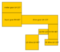
Since I want to be able to have multiple gears, some gearbox needs to be built. For this, a simple hi-lo layout has been designed. This is a non-synchronized design, so it remains to be seen if this works in practice. How this works: The motor will drive the motor gear. This gear drives the first reduction gear, and the axle of this reduction gear drives the gearbox. Using a servo, both LO and HI gearing can be chosen. The first prototype is also shown. Note that this does not yet have the motor attached. This will be added later and it will be mounted in the top cover of the gearbox.
Mechanical parts
Some prototypes of mechanical parts needed for the machine. First, an open differential. This prototype does not yet have a locking capability (this is done by locking one of the drive axles onto the ring gear). Another required part was a u-joint. This one has been made using 4mm locking nuts & metal rods (which eventually will be sealed in the pla), thereby allowing it to be secured onto a threaded rod.
Differential prototype
A working lockable differential has been built. Locking is done by sliding a lock between the axle and the ring gear (using a servo, not pictured below).
First complete-ish axle
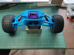
The first prototype of an axle has been completed. This includes the open/closed differential and driven wheels.
Differential
Subframe
The diff needs to be mounted in the subframe
Suspension
The suspension is bolted onto the subframe
Complete axle
And with all parts bolted on, it looks like this


