Nurduino: Difference between revisions
No edit summary |
|||
| Line 64: | Line 64: | ||
If this is your first time soldering: don't worry, it is actually not hard. I learnt it from [https://www.noisebridge.net/wiki/User:Maltman23 Mitch Altman], who is a great teacher and the co-author of [http://mightyohm.com/files/soldercomic/FullSolderComic_EN.pdf Soldering is easy]. | If this is your first time soldering: don't worry, it is actually not hard. I learnt it from [https://www.noisebridge.net/wiki/User:Maltman23 Mitch Altman], who is a great teacher and the co-author of [http://mightyohm.com/files/soldercomic/FullSolderComic_EN.pdf Soldering is easy]. | ||
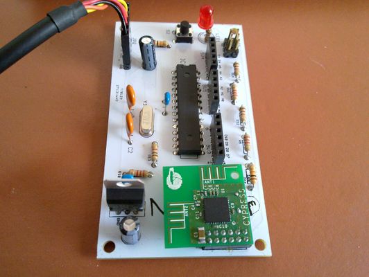
The PCB has markings for each specific component. The component table above contains these locations. The order in which you solder is not really important, apart from making it as easy as possible to reach each component while soldering. I suggest you start with the smaller resistors, capacitors and crystal. Then the headers and socket, larger capacitors and voltage regulator. The LED and pushbutton you can do whenever you feel like it. Use the picture above as a guide. | |||
If you soldered everything correctly, it is time to program the icu. Hook up the FTDI cable or FTDI friend and usb cable. It is important you have the oriëntation of the FTDI cable/friend correct. The pins on the board are marked. The GND pin should connect to the black wire on the FTDI cable. The VCC pin should connect to the red wire. This is really important, else you might fry the whole pcb. | |||
Revision as of 01:04, 27 March 2013
| NURDspace Project | |
|---|---|
| Participants | |
| Skills | |
| Status | |
| Niche | |
| Purpose | |
| Tool | |
| Location | |
| Cost | |
| Tool category | |
{{{Name}}}Property "Tool Name" (as page type) with input value "{{{Name}}}" contains invalid characters or is incomplete and therefore can cause unexpected results during a query or annotation process. Property "Tool Image" (as page type) with input value "File:{{{Picture}}}" contains invalid characters or is incomplete and therefore can cause unexpected results during a query or annotation process. {{{Picture}}} {{#if:{{{Tool}}} | [[Tool Owner::{{{ProjectParticipants}}} | }} {{#if:{{{Tool}}} | [[Tool Cost::{{{Cost}}} | }}
Nurduino is our very own arduino clone. It is the evolution of the Arduino Radio Spectrum Analyzer prototype on a breadboard project. In that project I built a prototype of the Nurduino, and tried to share the how's and why's. In this page I will make a shorted description of how to build the Nurduino kit, and use it as a 2.4GHz Radio Analyzer.
Attention (errata)
- At the LED1 location on the PCB the wrong hole is marked with a + sign. This is actually the GND hole. The other hole should contain the + leg of the LED.
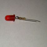
- In the PCB design, a mistake has been made by forgetting a resistor for the LED. We therefore soldered a 1k resistor to the + leg of the LED. For those who buy the kit complete, you receive a pre-assembled LED, so you don't need to worry. Others: please attach the resistor to the LED or you could burn out not only your LED but also your Atmega328 ICU!
What do I need
- A soldering iron (including sponge and stand). Use one that is accurate with a good tip. Although the pcb is setup with a lot of space there are a few spots where accuracy is required. Under €50 there are good options available.
- Solder. I use 0.7mm (more accurate then 1mm) with a resin core, containing lead (was your hands and try not to breathe the fumes).
- FTDI cable or FTDI friend (and micro usb cable) to connect the board to the usb port.
Software
- To program the atmega chip, you need this sketch.
- The full schematic and pcb design of the Nurduino can be found in this zipfile.
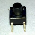
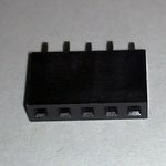
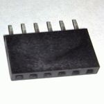
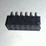
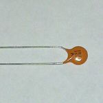
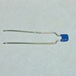
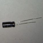
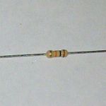
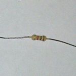
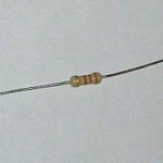
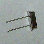
Kit components
Putting it together
If this is your first time soldering: don't worry, it is actually not hard. I learnt it from Mitch Altman, who is a great teacher and the co-author of Soldering is easy.
The PCB has markings for each specific component. The component table above contains these locations. The order in which you solder is not really important, apart from making it as easy as possible to reach each component while soldering. I suggest you start with the smaller resistors, capacitors and crystal. Then the headers and socket, larger capacitors and voltage regulator. The LED and pushbutton you can do whenever you feel like it. Use the picture above as a guide.
If you soldered everything correctly, it is time to program the icu. Hook up the FTDI cable or FTDI friend and usb cable. It is important you have the oriëntation of the FTDI cable/friend correct. The pins on the board are marked. The GND pin should connect to the black wire on the FTDI cable. The VCC pin should connect to the red wire. This is really important, else you might fry the whole pcb.

