Picknplacer: Difference between revisions
Jump to navigation
Jump to search
Print
| (2 intermediate revisions by the same user not shown) | |||
| Line 291: | Line 291: | ||
</driver> | </driver> | ||
</pre> | </pre> | ||
= Ramps, yo = | |||
[http://www.reprap.org/mediawiki/images/thumb/8/81/RAMPS_1.4.2.jpg/800px-RAMPS_1.4.2.jpg Ramps board layout] | |||
== Wiring == | |||
* Pump red: D9+ | |||
* Pump black: D9- | |||
* Solenoid green: D10+ | |||
* Solenoid brown: D10- | |||
= Special GCode = | |||
* Pump on: M42 P9 S255 | |||
* Pump off: M42 P9 S0 | |||
* Open Solenoid: M42 P10 S255 | |||
* Close solenoid: M42 P10 S0 | |||
= Misc info = | = Misc info = | ||
Latest revision as of 16:46, 20 October 2016
| Pick&placer | |
|---|---|
| Participants | |
| Skills | Electronics, Mechanics, 3D Printing, Programming |
| Status | Active |
| Niche | Hardware |
| Purpose | Instrument |
| Tool | Yes |
| Location | Nurdspace |
| Cost | TBD |
| Tool category | Fabrication |
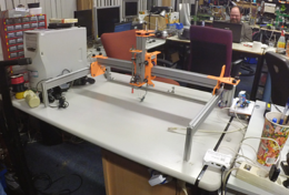
Picknplace-20160626.png {{#if:Yes | [[Tool Owner::{{{ProjectParticipants}}} | }} {{#if:Yes | [[Tool Cost::TBD | }}
Description
In 2015 we've made a ton of nurdnodes, which had been assembled by hand using a rudimentary tool. In order to produce many part prototypes, or make large productions runs, an automatic pick and place machine is imperative.
Design
Parts (unspecific)
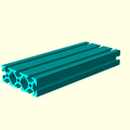
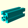
| makerslide | xlots | 0.02 EUR |
| HBLTSW5 brackets | 5x | ?? |
| V-wheel | ?x | ?? |
| 603VV | ||
| screws? | ||
| T slot bolts | ||
| idler wheels | ||
| cameras | x2 | $13.05 |
PNP Head
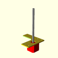
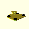
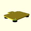
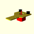
| PnP head middle plate | x1 |
| PnP head lower plate | x1 |
| Nema14 rotation stepper motor (14HM08-0504S) ? | x1 |
| M3-8 | x 4 |
| M3 washer | x 14 |
| M3 nut | x 5 |
| M3x6 | x 5 |
| M3 extrusion nut | x 2 |
| M3-20 | x2 |
| M4 nut (not M3) | x? |
| M5-12 bolt | x 2 |
| M5 washer | x 11 |
| M5 nut | x 2 |
| M5-8 | x? |
| M5-10 bolt | x 2 |
| M5 extrusion nut | x 3 |
| HTJ5 screw | x 2 |
* linear flanged bearing
| |
| HBLSD5 bracket ? | x 1 |
| HBLSS5 bracket ? ?? | x1 |
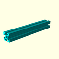
| MakerSlide | 250mm |
| Pick-up tube | x1 |
| M8 nylon washer | x 3 |
| GT2-36 pulley | x1 |
| GT2-60 belt loop | x1 |
| SCCN8-6 collar x 1 | |
| spring | x1 |
| Omron D3V-162-1C4 limit switch | 2x |
| WSSB12-3-1 washer | 1x |
| Flat spring | 1x |
X frame
Parts
- 20x20x767 alu extrusion
- M5-10
- M5 washer x 10
- M5-15 x 2
- M5 nut x 3
- M5-12
- M5 extrusion nut
- HBLSS5 bracket x2
- 140mm extrusion x3
- 20mm x 60mm extrusion, 140mm piece
- HTJ5 x8
- 500mm MakerSlide
- NEMA17 stepper motor
- Y motor mounting plate
- M3 washer x 4
- M3-6 x 4
- M5 extrusion nut x 2
- M5-8 x 2
- Y shaft support plate
- Flexible coupler
- Y axle tube
- SCCN8-6 shaft collar (4x)
- 608ZZ flanged bearing (6x)
- GT2-20 pulley, 8mm bore (2x)
Y pulley assembly
Everything x 2
- Y pulley plate
- 608ZZ flanged bearing
- M5-35 x 4
- M5-8 x 4
- M5-40 x 4
- M5 washer x 18
- M5 nut x 7
- M5 extrusion nut x 4
- Idler wheel subassembly x 4
- #16 aluminum spacer, 0.5″ x 4
- Y bearing plate
- 608ZZ flanged bearing
- SMBK5-30 spacer x 4
- Y idlers holder plate
Y roller plates
- Y roller left plate
- M5-10 low head
- M5-20 x 2
- M5-25
- M5-30 x 2
- M5 washer x 17
- M5 nut x6
- Eccentric spacer x 2
- V-wheel subassembly x 4
- HBLSS5 bracket
- Circular hook
- M4 nut
- M4 washer
- M4 washer
- M4 nut
- #12 aluminum spacer, 0.625″
TODO
Design
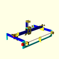
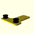
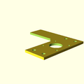
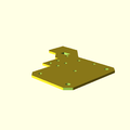
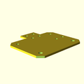
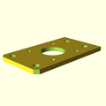
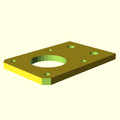
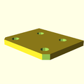
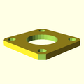
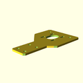
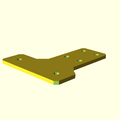
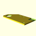
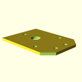
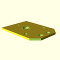
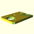
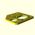
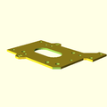
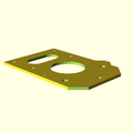
Gantry back plateGantry front platePnP head lower platePnP head middle platePnP head nut mount platePnP head top plateShaft support plateX idlers plateX motor plateY bearing plateY idlers holder plateY motor mount plateY pulley side plateY roller left plateY roller right plateZ motor mount plateAlign dragchain mounting points in z_motor_mount_plate and y_bar_right_roller- Mounting holes for dragchain
- Improve Y mounting points for plastic rather than metal (low priority)
Assemblies
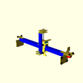
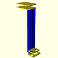
Y-barX idler platex motor plateY bar left roller plateY bar right roller plateGantry front plateGantry back platez motor plateGantryx frame
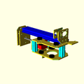
Gantry front plateGantry back platePnP head nut mount platePnP head top platePnP head middle platePnP head lower plate2x Y bearing plate2x Y idlers holder plate2x Y motor mount plate2x Y pulley side plateY roller left plateY roller right plateZ motor mount plateShaft support plateX idlers platex motor plate
Tasks
Assemble main frameAssemble baseAssemble machine housingProgram RAMPS firmwareReplace crimp connections of end-stop connectors with soldered connections- Calibrate RAMPS steps/mm all three axes
- Set traverse limits in firmware
- Attach frame to base
- Mount undercamera
- Tighten everything
- Complete vacuum/valve control
- Configure software for RAMPS
- Test place some pieces
- Test a board
Resources
- Design files: https://git.nurd.space/parallax/picknplacer.git
- http://store.amberspyglass.co.uk/ <- Makerslide source
- http://www.ebay.com/bhp/1ml-syringe
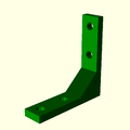
Part images
Pnp marlin driver specific config
<driver class="org.openpnp.machine.reference.driver.MarlinDriver" port-name="/dev/ttyACM0" baud="115200" feed-rate-mm-per-minute="5000.0">
         <pick-gcode>M106 S255</pick-gcode>
         <place-gcode>M107</place-gcode>
         <actuator-on-gcode>M8</actuator-on-gcode>
         <actuator-off-gcode>M9</actuator-off-gcode>
         <enable-gcode>M17</enable-gcode>
         <disable-gcode>M18</disable-gcode>
      </driver>
Ramps, yo
Wiring
- Pump red: D9+
- Pump black: D9-
- Solenoid green: D10+
- Solenoid brown: D10-
Special GCode
- Pump on: M42 P9 S255
- Pump off: M42 P9 S0
- Open Solenoid: M42 P10 S255
- Close solenoid: M42 P10 S0
Misc info
- A clone of the codebase is cloned into /home/common/picknplacer @printer-desktop for easy access when printing
Todo
- Create picture of RAMPS 1.4 connection scheme for PnP
