Arduino on a breadboard: Difference between revisions
No edit summary |
m (Text replacement - "Status=Finished" to "Status=Production") |
||
| (13 intermediate revisions by 3 users not shown) | |||
| Line 1: | Line 1: | ||
{{Project | {{Project | ||
|| | |Name=Breadboard Arduino | ||
| | |Skills=Electronics | ||
| | |Status=Production | ||
| | |Niche=Electronics | ||
| | |Purpose=Fun | ||
|Picture=arduino_breadboard1.jpg | |||
|Tool=No | |||
|ProjectParticipants=SmokeyD | |||
}} | }} | ||
==Atmega328 on a breadboard== | ==Atmega328 on a breadboard== | ||
Latest revision as of 08:53, 26 August 2014
| Breadboard Arduino | |
|---|---|
| Participants | Smokeyd |
| Skills | Electronics |
| Status | Production |
| Niche | Electronics |
| Purpose | Fun |
| Tool | No |
| Location | |
| Cost | |
| Tool category | |
arduino_breadboard1.jpg {{#if:No | [[Tool Owner::SmokeyD | }} {{#if:No | [[Tool Cost::{{{Cost}}} | }}
Atmega328 on a breadboard
These were the components I bought (or borrowerd here on the nurdpspace):
- 1x Atmega328 MCU with Arduinno bootloader
- 3x 2.2 KOhm resistor
- 3x 1 KOhm resistor
- 2x 10 KOhm resistor
- 1x reset switch
- 1x red LED
- 4x jumpers
- 2x 18pF ceramic disc capacitors
- 1x 16MHz crystal oscillator
- 1x CYWM6935 wireless USB radio module
- Any breadboard. I bought a small one since I thought I would have plenty of space, but I was mistaken, and would recommend a large one. The larger the better really.
- FTDI cable
- A plate full of spaghetti. Aka: solid core red wire
- A few cases of beer
- A few pizzas
The first step will describe the basic setup of an arduino on a breadboard (or rather an atmega328 MCU on a breadboard). For all you who have done this a million times arelady, just skip ahead, or even better, read it and correct me or give me suggestions on better ways of doing things. I will be eternally grateful.
I'll try not to explain too much, since others already did that better than I can, so instead I will point to some proper sources of information. First of all, take a look at an Arduino on a Breadboard. It is a good how-to on setting up an arduino on a breadboard. It might be that after reading that, you don't need me to tell you anything, but hey, I got time to spend tonight, so I'll write this up anyway.
This first step is just a very basic breadboard setup. The first step in wiring up a breadboard is finding the datasheets, or at least the pin mapping. The information in the datasheats is priceless. You can find the pinmapping of the atmega 328 on http://arduino.cc/en/Hacking/PinMapping168.
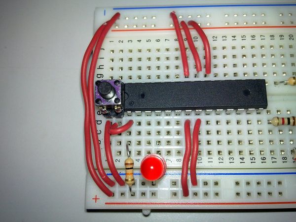
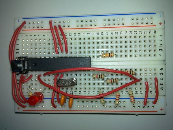
In this first image you can see I wired up the ground (GND) and positive lines (VCC) of the breadboard to the MCU. I also hooked up the Analog Reference (AREF), which tells the MCU what the highest voltage is for analog signals.
At the top of the breadboard I connected the positive and ground lanes to each other, so both sides are properly powered/grounded.
I also connected an LED to the digital pin 2 of the MCU, so you can test the MCU later on. I also use it in my programs, so I know that when the led blinks, the program is running.
The last part of the first step is the reset switch. If you want to program your MCU, you will need to tell it to reset, so it will be ready for programming. The MCU resets when a current flows away from the reset pin. So what you do is first connect a PULLUP resistor to the pin. This means that you connect a high resistance resistor (10kOhm in this case) to the positive line on the breadboard. This will make sure no current flows away unexpectedly from the reset pin, causing unexpected resets. Next you connect the same reset pin of the MCU to the reset switch, and you connect the other pin of the reset switch to the ground. Now when you press the reset switch, a current will start flowing from the reset pin of the MCU, to the ground, causing the MCU to reset.
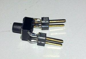
To the right you can see an image of what I did with the reset switch. It didn't want to stick in the breadboard because the legs were too short. So I soldered a jumper to each leg of the switch, so it had properly large legs, an fits nicely in the breadboard.
Before you can do anything with your breadboard, two more things need to be done: adding a crystal oscillator and adding connections for the FTDI cable (for power and for programming).
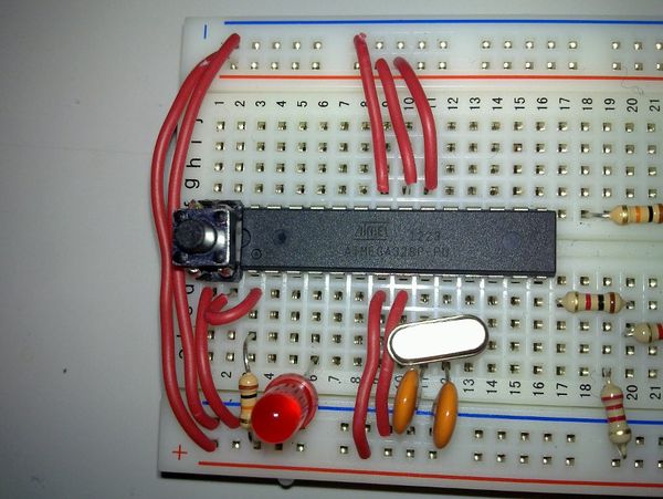
The crystal oscillator is the hardware clock of the MCU. You need a 16MHz crystal, with two capacitors. The crystal oscillates with 16 million oscillations per second. This is the speed at which the MCU can calculate and also drives the time measurement of the MCU. The crystal is connected to pins 9 and 10 of the MCU. In order to work, both legs of the crystal need to be connected to the ground through a capacitor. The needed capacitance of the capacitors had me stumped for a while. I still don't know the specifics, but on http://arduino.cc/forum/index.php?topic=5677.msg43967#msg43967 there is at least a reasonable explanation. In short, the needed capacitors depends on the crystal's specs, the board you hook it up to (the board itself also has capacitance) and on how important the accuracy of the crystal is to you. In the end I have ended up with two 18pF capacitors.
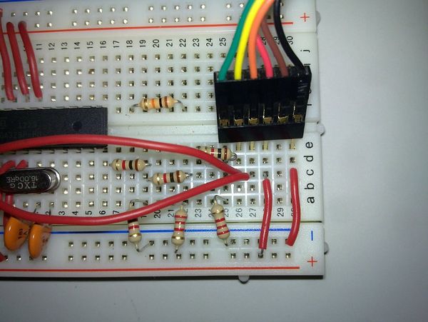
The last bit before you can start programming your arduino is hooking it up to your usb port. We will use the usb (FTDI) cable also for powering the breadboard. I left some free space at the left bottom of the breadboard for the TDFI cable. Just ignore the unconnected resistors in the image for now. They will be used later on. For now, you can see which pins I have connected of the FTDI cable. The red and black wires are 5V and GND respectively. So hook those pins up to the + and - lanes of the breadboard. The yellow and orange wires of the FTDI cable are the TX and RX cable, which take care of transmitting and receiving data from the usb port. These need to be connected to pins 2 and 3 of the MCU.
Now you can plug in the FTDI cable (I used some jumpers to connect it) and start programming.
If you bought a chip with a preloaded arduino bootloader, you can program it directly using the arduino IDE. If it is still blank, you will first need to burn a bootloader. Burning a bootloader (which can be done in several ways, I preferred putting my MCU in another arduino board that was lying around) is properly described towards the end of an Arduino on a Breadboard.
If you don't know what to do at all to program your MCU, I suggest you check out http://www.ladyada.net/learn/arduino/lesson1.html. I you do know how to start the Arduino IDE, some nice examples and good documentation can be found on http://arduino.cc/en/Tutorial/HomePage.
If you have the arduino IDE running, make sure you select the "Arduino Duemilanove with atmega 328" board. The port depends on windows or linux, but on linux it is probably /dev/ttyUSB0 for ubuntu based distro's.
As code for this board, I use the following code to program my MCU:
void setup() {
  // initialize the digital pin as an output.
  pinMode(2, OUTPUT);
}

void loop() {
  digitalWrite(2, HIGH);   // set the LED on
  delay(500);              // wait for 500ms
  digitalWrite(2, LOW);    // set the LED off
  delay(500);              // wait for 500ms
}
Once you see the led blinking, congratulations, you just built and programmed and arduino.
