GrundigRGBESP8266: Difference between revisions
No edit summary |
No edit summary |
||
| (2 intermediate revisions by the same user not shown) | |||
| Line 1: | Line 1: | ||
__NOTOC__ | |||
{{Project | {{Project | ||
|Name=Grundig RGB lamp with ESP8266 | |Name=Grundig RGB lamp with ESP8266 | ||
|Skills=Electronics, Programming, | |Skills=Electronics, Programming, | ||
|Status= | |Status=Done | ||
|Niche=Electronics | |Niche=Electronics | ||
|Purpose=Infrastructure | |Purpose=Infrastructure | ||
|Picture= | |Picture=Esp8266-breadboarded.jpg | ||
|Tool=No | |Tool=No | ||
|Location= | |Location= | ||
| Line 19: | Line 20: | ||
* ???? | * ???? | ||
* Profit! | * Profit! | ||
== build log == | |||
<gallery> | |||
Grundigesp8266-working.jpg | |||
Grundigesp8266-ledarrangement.jpg | |||
Grundigesp8266-internals.jpg | |||
Grundigesp8266-pinoutnotes.jpg | |||
</gallery> | |||
Right, whatever. I pulled all electronics out, soldered a Wemos D1 mini inside and 10x SK6812RGBW leds and i used my existing art-net code. Done :D | |||
--[[User:Buzz|buZz]] ([[User talk:Buzz|talk]]) 21:34, 1 October 2016 (CEST) | |||
Inspired by madeddie's ESP mission, i dug up this old project and attempted to finish it. | |||
Had it working on breadboard so moved to put it inside the actual lamp. Doing so I seem to have broken ~something. Currently debugging. | |||
<gallery> | |||
Grundig-lamp-wiremess1.jpg | |||
Grundig-lamp-wiremess2.jpg | |||
Grundig-lamp-wiremess3.jpg | |||
</gallery> | |||
--[[User:Buzz|buZz]] ([[User talk:Buzz|talk]]) 19:20, 14 November 2015 (CET) | |||
== control mcu pinout == | == control mcu pinout == | ||
| Line 45: | Line 73: | ||
* https://www.conrad.nl/nl/grundig-rgb-mood-light-grundig-rgb-led-verlichting-mood-light-meerkleurig-1000346.html | * https://www.conrad.nl/nl/grundig-rgb-mood-light-grundig-rgb-led-verlichting-mood-light-meerkleurig-1000346.html | ||
[[Image:Grundig_RBG_Mood_Light_PCB.jpg|250px]] | |||
Latest revision as of 20:34, 1 October 2016
| Grundig RGB lamp with ESP8266 | |
|---|---|
| Participants | User:buzz |
| Skills | Electronics, Programming |
| Status | Done |
| Niche | Electronics |
| Purpose | Infrastructure |
| Tool | No |
| Location | |
| Cost | |
| Tool category | |
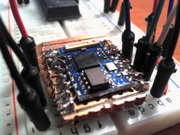
Esp8266-breadboarded.jpg {{#if:No | [[Tool Owner::{{{ProjectParticipants}}} | }} {{#if:No | [[Tool Cost:: | }}
the plan
- Disable the shitty mcu inside the lamp (done)
- Solder wires to the vcc, gnd and pwm pins (nearly done)
- Connect a ESP8266 to it with nodemcu and some lua sauce
- ????
- Profit!
build log
Right, whatever. I pulled all electronics out, soldered a Wemos D1 mini inside and 10x SK6812RGBW leds and i used my existing art-net code. Done :D
--buZz (talk) 21:34, 1 October 2016 (CEST)
Inspired by madeddie's ESP mission, i dug up this old project and attempted to finish it.
Had it working on breadboard so moved to put it inside the actual lamp. Doing so I seem to have broken ~something. Currently debugging.
--buZz (talk) 19:20, 14 November 2015 (CET)
control mcu pinout
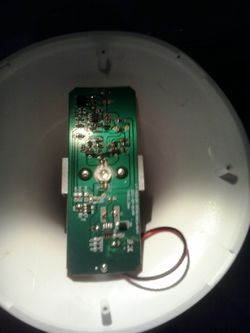
This is the unmarked IC labelled U1 on the silkscreen. , vcc is 4.24-4.3 volts
               -------------
              |   o         |
 vcc      ----| 1         5 |----  gnd
 red pwm  ----| 2         6 |----  blue pwm
 ?        ----| 3         7 |----  green pwm
 ir rx    ----| 4         8 |----  ?
               -------------
Funny bit is, the PWM signal is actually inverse. So they output a high signal to turn off the LED, and a low signal to turn on the LED. This can be proven by grounding one of the pwm output pins, which turns on the respective color of LED.
consideration
- Make wifi foolproof, webpage style config and 'robust'
- Do fancy fades inside the ESP8266 ?
- Lower voltage a bit (about 0.7V?) to power the ESP8266
- Pray the pwm output has enough umpf
links


