Bb-leds: Difference between revisions
No edit summary |
(→beaglebone: photo and note on pinout of power) |
||
| Line 16: | Line 16: | ||
== beaglebone == | == beaglebone == | ||
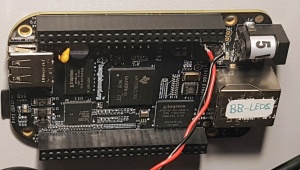
[[File:bb-leds-power.jpg|300px|right]] | |||
2022-12-31 Flashed with a basic debian bullseye system. | 2022-12-31 Flashed with a basic debian bullseye system. | ||
| Line 22: | Line 24: | ||
* password: <code>777</code> | * password: <code>777</code> | ||
This beaglebone is missing its mini-usb port but can be powered via the P9 header using included cable ( | This beaglebone is missing its mini-usb port but can be powered via the P9 header e.g. using included cable (see photo). | ||
For reference, the power pins of the beaglebone: | |||
* P9.01 + P9.02 = GND | |||
* P9.03 + P9.04 = 3.3V out (unused) | |||
* P9.05 + P9.06 = 5V in | |||
* P9.07 + P9.08 = 5V out (to level shifter) | |||
== level shifter == | == level shifter == | ||
Revision as of 19:03, 1 January 2023
| BB-leds | |
|---|---|
| Participants | |
| Skills | Electronics |
| Status | Getting parts |
| Niche | Hardware |
| Purpose | Fun |
| Tool | No |
| Location | shelves next to studio |
| Cost | |
| Tool category | General |
BB-leds Property "Tool Image" (as page type) with input value "File:{{{Picture}}}" contains invalid characters or is incomplete and therefore can cause unexpected results during a query or annotation process. {{{Picture}}} {{#if:No | [[Tool Owner::{{{ProjectParticipants}}} | }} {{#if:No | [[Tool Cost::{{{Cost}}} | }}
Monochrome LED tickers donated from ]LAG[
- 2 boards * 3 text lines * 7 rows * 90 columns
- Boards have been reverse-engineered (TODO document on wiki)
- One board is missing the PNP transistor for one of the seven rows
beaglebone
2022-12-31 Flashed with a basic debian bullseye system.
- hostname:
bb-leds - login:
debian - password:
777
This beaglebone is missing its mini-usb port but can be powered via the P9 header e.g. using included cable (see photo).
For reference, the power pins of the beaglebone:
- P9.01 + P9.02 = GND
- P9.03 + P9.04 = 3.3V out (unused)
- P9.05 + P9.06 = 5V in
- P9.07 + P9.08 = 5V out (to level shifter)
level shifter
A 3.3V to 5V level shifter is needed (3 signals per board, can probably be optimized to 4 signals total for both boards if they're driven synchronously). As a temporary hack a beestore pro mini from User:flok has been programmed to act as a 6-ch level shifter with pinout:
- PC0 ("A0") → PB0 ("D8")
- PC1 ("A1") → PB1 ("D9")
- PC2 ("A2") → PB2 ("D10")
- PC3 ("A3") → PB3 ("D11")
- PC4 ("A4/SCL") → PB4 ("D12")
- PC5 ("A5/SDA") → PB5 ("D13")

