GrundigRGBESP8266: Difference between revisions
Jump to navigation
Jump to search
No edit summary |
No edit summary |
||
| Line 1: | Line 1: | ||
{{Project | {{Project | ||
|Name=Grundig RGB lamp with ESP8266 | |Name=Grundig RGB lamp with ESP8266 | ||
|Skills=Electronics, Programming, | |Skills=Electronics, Programming, | ||
|Status=Planning | |Status=Planning | ||
|Niche=Electronics | |Niche=Electronics | ||
|Purpose=Infrastructure | |Purpose=Infrastructure | ||
|Picture= | |Picture=Grundig_RBG_Mood_Light_PCB.jpg | ||
|Tool=No | |Tool=No | ||
|Location= | |Location= | ||
| Line 11: | Line 11: | ||
|Category= | |Category= | ||
}} | }} | ||
== control mcu pinout == | == control mcu pinout == | ||
Revision as of 20:17, 31 January 2015
| Grundig RGB lamp with ESP8266 | |
|---|---|
| Participants | User:buzz |
| Skills | Electronics, Programming |
| Status | Planning |
| Niche | Electronics |
| Purpose | Infrastructure |
| Tool | No |
| Location | |
| Cost | |
| Tool category | |
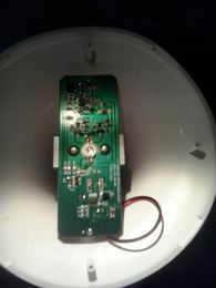
Grundig_RBG_Mood_Light_PCB.jpg {{#if:No | [[Tool Owner::{{{ProjectParticipants}}} | }} {{#if:No | [[Tool Cost:: | }}
control mcu pinout
This is the unmarked IC labelled U1 on the silkscreen. , vcc is 4.24-4.3 volts
               -------------
              |   o         |
 vcc      ----| 1         5 |----  gnd
 red pwm  ----| 2         6 |----  blue pwm
 ?        ----| 3         7 |----  green pwm
 ir rx    ----| 4         8 |----  ?
               -------------
Funny bit is, the PWM signal is actually inverse. So they output a high signal to turn off the LED, and a low signal to turn on the LED. This can be proven by grounding one of the pwm output pins, which turns on the respective color of LED.
