Timelapse rig: Difference between revisions
No edit summary |
mNo edit summary |
||
| Line 4: | Line 4: | ||
|Niche=Electronics | |Niche=Electronics | ||
|Purpose=Electronics, fun, world domination | |Purpose=Electronics, fun, world domination | ||
|Picture=Pcb_timelapse.png | |||
|Tool=No | |Tool=No | ||
|Cost=10 euroish | |Cost=10 euroish | ||
Revision as of 22:41, 14 September 2019
| Timelapse rig for Prusa MK3 3d Printer | |
|---|---|
| Participants | |
| Skills | |
| Status | Active as fuck |
| Niche | Electronics |
| Purpose | Electronics, fun, world domination |
| Tool | No |
| Location | |
| Cost | 10 euroish |
| Tool category | Electronics |
Timelapse rig for Prusa MK3 3d Printer
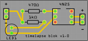
Pcb_timelapse.png {{#if:No | [[Tool Owner::{{{ProjectParticipants}}} | }} {{#if:No | [[Tool Cost::10 euroish | }}
Project:
Timelapse rig for Prusa MK3 3d Printer
The idea: A small box with some electronics that is connected with the EINSY RAMBO board of the printer and a remote shutter cable coming from the camera.
Why?: To make timelapses with a DSLR camera for fun.
Purpose: see why? Also for showing off and
First steps: So I found the idea on a prusa blogpost and wanted to create something like that, they only had an example for a lumix camera wich was of no use because I have a canon 1200D.
In the same blog there is a link to a site that shows the pinouts for different remote shutter cables with that I can go futher with the project
Blogpost: https://blog.prusaprinters.org/how-to-create-beautiful-3d-print-timelapse-videos/ Camera pinouts: http://www.doc-diy.net/photo/remote_pinout/
Getting the parts: well already got all the parts I need at Nurdspace except for the optocoupler I ordered the 4N25 from https://sinuss.nl/componenten/opto-elektronica--displays/optocouplers/transistor-output/1225849-4n25shortoptocoupler-transistor-optoshiba
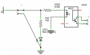
then I got some help from Danieltoo who learned me how to read schematics and some other stuff.
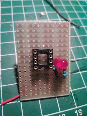
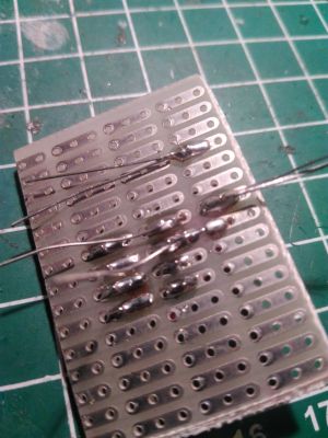
Preparing: I made a quick build with some protoboard and the parts. Front:
Back:
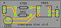
Going from dafuq to overdrive: after seeing the protoboard I said to myself you can do better, design a pcb even if you havent done it before.
So said so done I made the pcb in about a hour and a half because I was not familiar with the program Fritzing or even making pcb´s at all. first i made the schematics after making them i neatly put all the parts just right on the pcb
After making the pcb´s in Fritzing I ordered 10 of the pcb´s at https://jlcpcb.com/ in black for about 5 euro total inc shipping because of first time customer no shipping costs.
