NurdNode: Difference between revisions
| Line 121: | Line 121: | ||
== Software == | == Software == | ||
* <s>Create some spiffy code to make the blinkenlichten go blink blink.</s> | * <s>Create some spiffy code to make the blinkenlichten go blink blink.</s> | ||
* Design standalone mode | * <s>Design standalone mode</s> | ||
* Change firmware so pin 1 is used to toggle DMX and standalone mode | * <s>Change firmware so pin 1 is used to toggle DMX and standalone mode</s> | ||
* Review firmware | * Review firmware | ||
* Fix issues | * Fix issues | ||
Revision as of 16:02, 8 August 2015
| NurdNode | |
|---|---|
| Participants | Cha0z97, User:petraea |
| Skills | Electronics, Programming |
| Status | Planning |
| Niche | Electronics |
| Purpose | Fun |
| Tool | No |
| Location | |
| Cost | |
| Tool category | |
Pinout prodnode.png {{#if:No | [[Tool Owner::{{{ProjectParticipants}}} | }} {{#if:No | [[Tool Cost:: | }}
Description
The goal is to build wireless nodes that will control a bunch of LED's for cool lighting effects. The ultimate cool is to build enough, so we can put them in the connector pieces of our geodesic dome
Hardware design considerations
1 node will draw around 1A in current. For 31 nodes, this is obvisouly 31A in current at 5V, making the total power consumption 155W at full load. The current proposition is to bundle the power and signal lines into one cable, and run them in an upward spiraling fashion across each node, connecting them serially. The benefit of this setup is that it allows for easy addressing and it's simple. However, running 31A through a single power line requires a big, heavy and expensive cable.
The length of the power lines is determined at 60m. According to this site [1], at 3% acceptable loss, and using 5V at 31A the cable crossection is 16m2. A ballpark price estimate using Eijlander as supplier is roughly 330 euro.
An alternative would be to devide the power distribution into several groups. The upside is that we can get away with thinner cables, but we may require longer cables.
Yet another alternative is to raise the voltage of the grid to 12+V. This means we may use thinner power lines and still use the serial wiring setup. However, each node will have to be equipped with a switching power source to keep power dissipation at its lowest. This circuit will come at an extra cost, and having 31 nodes, this could escalate quickly.
(Why not elevate voltage a lot more, say 48V? Would reduce the current by an order of magnitude without adding more parts. Talloak (talk) 00:44, 4 May 2015 (CEST) )
Pinout of prototype
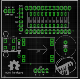
To connect the LED, hook up the wires to the corresponding channels. The + of the LED can be hooked up to either of the three + s. The design is a bit wonky, so that's why you get 3 + pins whereas only one is needed. The TX/RE/RX pins are used for debugging. Nothing is to be hooked up to those pins. The servo's need the lower 2x3 pins. I believe the diagram speaks for itself in this respect. Pin A and B are the DMX signal wires. Make sure all the A's are hooked up together as well as all the B's
Pinout of final version
Parts selection
IRL540 for power led stages?
TODO
Hardware
Calulate total length of cable required to connect all nodesCalculate price of power linesDesign power circuitDesign LED circuit (for optional leds)Design power stage for 3W ledSelect appropriate through-hole parts for breadboardingOrder thru-hole partsBuild thingamagic on breadboardSelect appropriate SMD parts for the final device.Select decoupling capsSelect connectorsSelect N-channel MOSFET
Design boardAssemble BOMDetermine pinout of PSUCreate pinout of prototype nodeBuild first prototypeTest first prototypeTest out smaller FET as replacement for the fat bastardsFix design mistakesFinalise designUpdate BOMBuild device that will zero in the Servo'sBuild device that tests the channels of the LED separately.Assemble 35 Pro mini'sLabel 35 pcb's with numbers 1-100 AFTER they have been in the oven ;)Program 35 Pro mini's with firmware.Calibrate 35 PSU'sCut 100 heatsinksDrill 100 heatsinksSolder 35 LEDs to jumper wire in the following order +RGBTest channels of 35 LEDsStick 35 LEDs to heatsinksGlue 35 heatsink + LED combination to servo arm.Glue 35 lenses to LEDsPick and place 100 nodesSolder through hole parts to 35 nodesZero-in servo's of 35 nodesScrew servoarm + heatsink + led to servo.Set address of 31 nodesTest address of 31 nodes by hooking it up to the DMX bus and try to talk to it using its addressStick Pro-mini on 35 nodesSolder calibrated PSU on 35 nodes- Create building instructions
Test 65 board for shorts and open connectionsAssemble 65 kits- Provide documentation for kits
Cabling
Determine guage of power cablesDetermine which signal wires to useGet wires at ijlander, or orderBuild cable - power sectionBuild cable - signal section
Total cable length based on 10M dome = 31 - 1 * 2m = 60m
1mm2 stereo cable will be used for the supply of power
Fancy sensor cable is used for transport of signal
Ordering
100 pcs 3W Led100 pcs PSU100 Pro mini's200 Servos100 Lenses110 Jumper cables for soldering to LED3x solder pastePrototype StencilPrototype PCB'sEnough material for prototypesMetal framed stencil for final designFinal PCB'sMore molex connectorsEnough materials for final nodesAdhesive for LEDsExtra transmitter chips (after validation)
Software
Create some spiffy code to make the blinkenlichten go blink blink.Design standalone modeChange firmware so pin 1 is used to toggle DMX and standalone mode- Review firmware
- Fix issues
- Mark firmware as final
- Create a C&C lib that organises the nodes and takes care of the comms between the nodes and the higher level software. I'm thinking REST API for the higher level stuff and UDP multicast for the lower end. Suggestions welcome.
- Find a tool (better yet DIY) a tool that allows you to define an animation in 3D and project it on the geodome.
Testing
Individual nodes
- #19's power supply just stopped working.
- #19 - power is shorted to ground somewhere on the board. Might be on the PSU.
- Additional investigation required. Failure is generally caused by a high current, which would indicate a short on the board.
- T2 shorted - fixed
- #16 looks to have a blown power converter.
- Possible short between GND and PWR
- #5's Green channel looks funny from that tesy
#5 - Either R4 or R8 is a problem- FIXED
- #7's green is shorted
- FIXED
- T4 shorted
- #8 has a shorted green
- #8 - T5 is shorted
- #15 has an addressing problem with the middle pin.
#15 is missing R10- FIXED
- #10 has the same addressng problem
#10: DIP #4 is connected to 5VThere is a short under the 3.9k resistor on dip 4 on #10- FIXED
- #28 has no address at all - all 0's.
#28 - R23 short, R20, R10 short.- FIXED
- #27's lowest address pin is not working.
- #27
R24 is not connectedR24 has been connected - FIXED
- #27
- #17's green is shorted and red is disconnected.
- #17 - T1 and T5 shorted
- #14's address is all 0's.
- Possible short under R20
- Possible disconnect
11 / 35 failures
Cable
- Build cable tester (res + led) * 2 on molex connector to test power line and signal line
- Unreel entire cable
- On the controller end, check for shorts between the 4 wires. There should be none. If there are, good luck finding, as this may take a while.
- Apply 5V across PWR and ground.
- Place tester on each molex, checking if the PWR led lights up.
- Disconnect PWR and ground from voltage source.
- Apply 5V across SIG A and SIG B. Keep in mind the orientation of the tester.
- Place tester on each molex, checking if the SIG led lights up.
- Disconnect SIG A and SIG B from voltage source.
- If a led does not light up; this could be
- Failing connection
- Miswiring
- Check for miswiring first to rule out the easiest to diagnose, then proceed to determine the cause of the failing conncection.
If both LEDs have lit up on all sockets, the cable should be fine.
Production boards
- Find a production board with soldering flaw
- Reflow the board full cycle (up to 250 deg)
- Check if the soldering flaw has been resolved.
- Visually inspect the board for crispyness
- Assemble board to take the place of one of the fried ones meant for the dome.
If test sufficient:
- Reflow all remaining boards full cycle
- Test all board for shorts between +5 and GND and visually inspect.
- If reflowed and tested, board may be sold
- If issues remain, discard board.
If test insufficent:
- Deliberate
Website
- setup host under nodes.nurdspace.nl
- Make page with general information + assembly instructions
- Include link to repos for firmware
- Include link to repos for hardware design
- Include link to repos for STL's
Production unit packing list
Accesory bag
- 1 10-way DIP switch
- 8 header pins / PSU
- 1 3300uF cap
- 3 3-way male header pins
- 1 4-way male header pins
- 2 12 pin female headers
- 1 MOLEX connector socket
- 1 MOLEX plug
- 4 crimp connectors for molex
- 1 LED
- 4 M3x15 screws
- 2 mini servo head screws
- Sticky LED coolant patch
Main bag
- SMD'd board
- 1 pro-mini kit
- 1 Assembled PSU or 1 PSU kit
- 1 LED wire
- Printed body
- Servo body + 2 servos
- Ziptie
- Servo foot
- Lens
- Heat sink head
- Information to get further information
- Disclaimer stating the experimental nature of the device
Pricing
- 30 E including tax for a single unit
- 150 E (inc) for a pack of 5 units + free USB 2 DMX transmitter
Return policy
- Board broken? Money back or replacement. Depending on the wish of the customer.
Links
- Potential 24V power supply: http://www.ebay.com/itm/321660472921
- Or 48V?: http://www.ebay.com/itm/261847060063
- Step down from 24V: http://www.ebay.com/itm/171381728637
- Leds: http://www.ebay.com/itm/191388798412
- Or: http://www.ebay.com/itm/221544924178 with added heatsinks onboard.
- Extra heatsinkery: http://www.ebay.com/itm/331286129263
- Sticky pads for connection: http://www.ebay.com/itm/121331880334
- Interesting source of servo's: http://www.giantshark.co.uk/product/167511/towerpro-sg90-9g-micro-servo - with returns in the UK. Promising!


