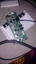
Korg Monotron Eurorack Mod: Difference between revisions
mNo edit summary |
mNo edit summary |
||
| Line 13: | Line 13: | ||
* Remove battery terminals from PCB | * Remove battery terminals from PCB | ||
* Remove audio jacks? | * Remove audio jacks? | ||
* Remove R10 | |||
* Design and build a board with the desired in- and outputs and controls, probably on protoboard (called ''I/O board'' from this point on) | * Design and build a board with the desired in- and outputs and controls, probably on protoboard (called ''I/O board'' from this point on) | ||
* Build a simple board for powering the module (called ''power board'' from this point on) | * Build a simple board for powering the module (called ''power board'' from this point on) | ||
Revision as of 21:12, 28 December 2018
| Korg Monotron Eurorack Mod | |
|---|---|
| Participants | Dennis |
| Skills | Soldering |
| Status | Planning |
| Niche | Electronics |
| Purpose | Instrument |
| Tool | No |
| Location | |
| Cost | |
| Tool category | |
Monotron PCB Front.jpg {{#if:No | [[Tool Owner::{{{ProjectParticipants}}} | }} {{#if:No | [[Tool Cost::{{{Cost}}} | }}
What
The idea is to make a eurorack module out of the Korg Monotron synthesizer. The Monotron synths are extremely hackable, Korg released the schematics and a lot of people have published mods. I have the original Monotron. I want to be able to reuse the existing pots and microswitch, so they will stick through the faceplate.
Todo
- Remove battery terminals from PCB
- Remove audio jacks?
- Remove R10
- Design and build a board with the desired in- and outputs and controls, probably on protoboard (called I/O board from this point on)
- Build a simple board for powering the module (called power board from this point on)
- Design and build a faceplate
- Assemble everything together and put it in a eurorack case
Thonkiconn mono jack sockets
I will be using Thonkiconn connectors since I've got a load of them and they are easy to work with on protoboard. Datasheet can be found here: https://www.thonk.co.uk/wp-content/uploads/2014/02/Thonkiconn_Jack_Datasheet.pdf
Signal will go on pin 3, and ground on pin 1.
The I/O board
Mono jack inputs
See http://electro-music.com/forum/phpbb-files/monotron_mods_181.jpg for connections of most of this.
Pitch CV in
Controls the pitch of the VCO.
Gate in
Can turn the sound on and off, most probably influencing what's coming out of the Audio out only, not the VCO out.
Cutoff CV in
Controls the cutoff frequency of the filter.
LFO rate in
There is a pad on the Monotron PCB called rate.
Audio in
Possibly use two mono ins and hook it up to the stereo in on the Monotron PCB.
Mono jack outputs
Audio out
VCO out
Connect directly to Monotron PCB, pad is marked VCO.
LFO out
Connect directly to Monotron PCB, pad is marked LFO.
Controls
Switch
Toggles pitch tracking of the filter cutoff frequency
Pitch CV tune pot
Cutoff CV amount pot
Adjusts the amount of influence the CV has over the filter cutoff.
The power board
This will be fairly simple. It will have a 10-pin connector for the ribbon cable to the eurorack busboard. Only 5V and ground will have to be connected to the Monotron PCB. Since the connector has a notch, there is low risk of hooking it up incorrectly but I might decide to have a protection diode somewhere anyway.
Links
- http://electro-music.com/forum/topic-57134.html
- http://www.dinsync.info/2010/06/how-to-modify-korg-monotron.html
- http://beatnic.jp/?s=monotron%2B%2B
- http://masa921.sitemix.jp/monotron_mod.htm
- http://pjmnc.free.fr/files/midiTron.JPG
- https://ua726.co.uk/2011/01/05/korg-monotron-hacking/
- http://www.marc-nostromo.com/midi-control-for-the-monotron-using-a-teensy-3-0/
- http://pulplogic.com/permutations/monotron-e-convert/
