T119RC-Bert
| T-119RC "Bert" | |
|---|---|
| Participants | |
| Skills | |
| Status | Active |
| Niche | |
| Purpose | |
| Tool | No |
| Location | R3boots home |
| Cost | |
| Tool category | |
T-119RC "Bert" Property "Tool Image" (as page type) with input value "File:" contains invalid characters or is incomplete and therefore can cause unexpected results during a query or annotation process.
{{#if:No | [[Tool Owner::{{{ProjectParticipants}}} | }} {{#if:No | [[Tool Cost::{{{Cost}}} | }}
What
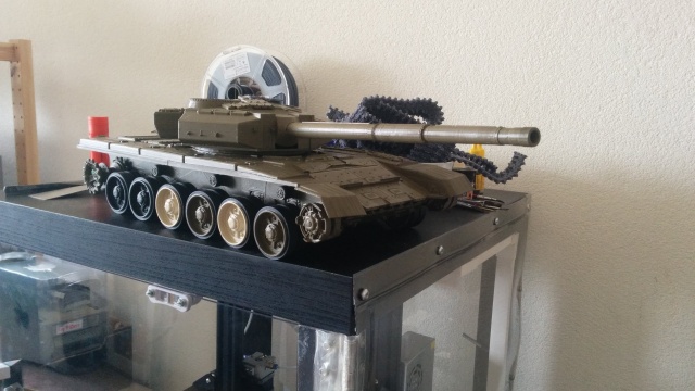
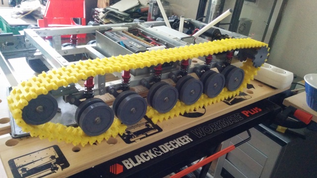
A remotely controlled tank chassis.
Why
My Grandfather was a tank commander, and ever since I was a kid, I have been impressed with large vehicles. Also, as a kid, I did a lot of modelling. So while I was building a scale model of the T90, I got the inspiration to build my own remotely controlled tank chassis.
How
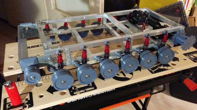
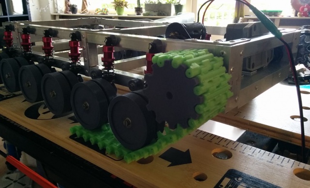
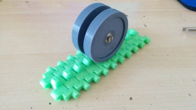
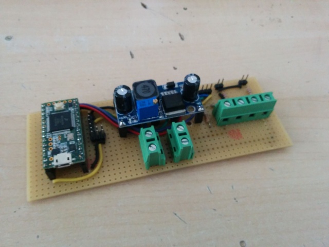
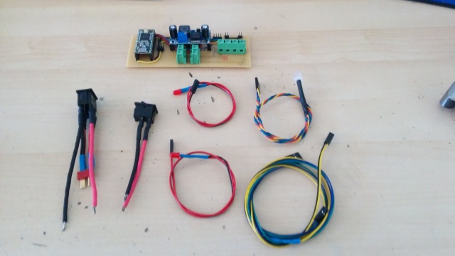
This project started with an RC suspension component. Using that, I gradually designed a tank around it. The tank itself has been built using a mix of techniques. The chassis is made using aluminium profiles bought from the Gamma and bound together using rivets. All moving parts have been made using 3d printing. The motors come from spare parts from Henglong RC tanks and the control was originally part of an RC helicopter/aircraft. Arduino-based electronics have been added to translate the aircraft controls to tank controls
Story
I have designed this using an iterative design process and a lot was done using learn-as-you-go. After working on this project for approx 4 months, I broke it within 45 minutes. This was caused by not caring about tolerances as I should :) This caused most of the drivetrain to be redesigned in order to have all axles straight. Once this was fixed, further testing took place. Not all individual tracklinks were printed as well as I would imagine, and this caused the tracks to break in certain situations. This was also fixed by replacing the faulty tracks.
Design files and Code
All parts have been designed using solidworks. The original design files can be found here. The code that lives on the controller, together with some schematics can be found in this file. No digital design has been made wrt the schematics.
POIDH!
It works! It bloody works!!! https://imgur.com/gallery/44u2C6t
The first attempt at a box for the receiver & antennas: https://imgur.com/gallery/ewsNx4y
The box containing the receiver was not designed all that well, so I redesigned it: https://imgur.com/gallery/vcPdTFx
I was *so* glad when this batch was finished. It is hard to explain how much effort went into the tracklinks: https://imgur.com/gallery/JLBhGmp
Once all these steps are done, and after approx 3 months of building, it was finally time to test the chassis for the first time. https://imgur.com/gallery/PIUKGsA
A failed experiment in creating a housing for the reduction gear using available spare parts: https://imgur.com/gallery/TX07kdV
The pins connecting the tracks would walk once you drove the tank. This caused the pins to extrude, and this in turn hooked onto other parts of the chassis, causing breakage: https://imgur.com/gallery/g7Tmkge
This was fixed by welding the metal pins in place in the track links by adding a little piece of plastic on top. https://imgur.com/gallery/uJNw4w7
On top of that, the motor mounts were redesigned and strengthened https://imgur.com/gallery/NmpRaou
Once I was at this point, the chassis was pretty stable, except for some weak track links: https://imgur.com/gallery/GYya8Ca
Finally, the chassis was finished, and its time to play with it! https://imgur.com/gallery/OeyKc41

