OdroidBladeServer
| Odroid Blade Server | |
|---|---|
| Participants | |
| Skills | 3D design + printing, Electrics, Soldering |
| Status | In Progress |
| Niche | Hardware |
| Purpose | Holding server mainboards |
| Tool | No |
| Location | |
| Cost | |
| Tool category | |
Odroid-blade-server.jpeg {{#if:No | [[Tool Owner::{{{ProjectParticipants}}} | }} {{#if:No | [[Tool Cost::{{{Cost}}} | }}
Introduction
I've been tinkering with a k3s cluster for a while now, and I finally managed to get my 'dream' configuration to run properly. The current cluster is running on a set of virtual machines, and then a colleagure of mine mentioned the existence of the Odroid H3 and while looking at the specs and price it quickly turned out that these systems would make perfect cluster nodes for my k3s cluster. Thing is, there are only cases available for single-node odroids (and one way too expensive 3 node cluster one, but that wasnt to my liking), so I figured, lets build my own :)
Concept
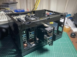
Inspired by blade server architecture, I figured I should make a rail-based system, allowing me to quickly swap a mainboard if one would ever break. The initial idea was to create my own case by using an aluminium frame covered with plexiglass/polycarbonate plates, but that idea quickly went away since I dont have xs to tools allowing me to cut either material to the sizes I'd need. So the next idea was to find some existing casing, and modify that in such a way that it would fit my purpose. I considered a bunch of casings, ranging from a samla to an old VAXstation case, until I ran into an old Mini ITX casing at the space. The system was big enough to carry three boards, cooling and a power supply, and so I took it home and stripped it to its bare essentials, and the design process started. I made the following design decisions in doing this:
- Externally, you should not be able to see the case has been modified
- The system should be functional, clean and easy to use
- Usage of high-quality components and techniques
- No shortcuts
- Mainboards should be loaded from the side
Design
The idea is to have three odroid h3's in the case. The case also contains a 15V power supply used to power the odroids. The odroids have two 2.5GE interfaces; The first one is used to connect to the external network, and is fed towards three connectors mounted on the IO plate in the back of the case. The second interface is used for cluster communication, and is connected to a 5 port unmanaged gbit switch which is mounted inside of the case. Since the switch needs a 5V power supply, and I did not want to use a DC-DC converter, I opted to install a 5V power supply as well. All fans attached to the case will also be fed with this power supply, allowing a separate system for cooling.
The idea with the rails system was that I could easily disconnect the power + network cables, move them out of the way, and slide out/in the bracket. But, since both the power button and power led are mounted on the io expansion header (which is mounted in an awkward place), this meant I had to find a solution to make this easy to (dis)connect. Eventually I opted for using magsafe connectors mounted on the back (front?) of the bracket. This both allowed me to 'lock' in the brackets using magnets, but also that I had 5 pins I could use to transport signals from the board to the case in a clean way. Since I needed three pins for the power switch + led, I had two pins left. The idea was to connect the RX/TX signals of the onboard uart of the odroids to a converter board with a max232, but since I could not find a clean and functional place for the converters, I opted to drop this idea.
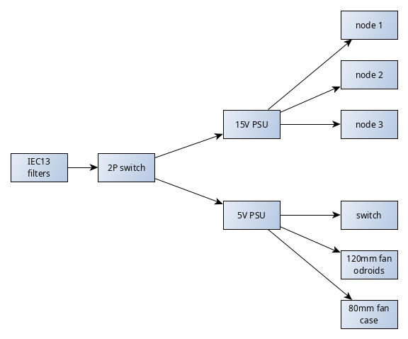
The power system should have a single 230V inlet with filters on it, and a switch which (dis)connects both L and N. All cables will be fed towards a junction box, and from there it splits off towards both power supplies. The output of the psus is fed back into the junction box, and from there distributed to the places where the voltage is needed.
Implementation
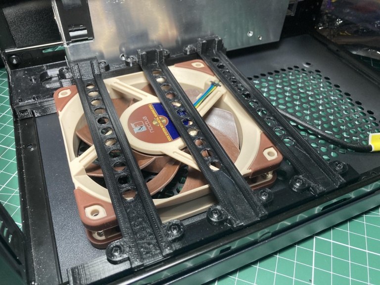
The decision to load the system from the side came from the design of the case. The top + bottom cover came with a mount system + holes for a 120mm fan. Since the odroid boards measure 110x110mmx50mm, this meant I could use a single fan to cool all of the boards at the same time. I decided to place the fan in the bottom blowing upwards, to prevent dust from settling in on the system. Since the 120mm fan has a fixed position, I used this as the zero-point in designing the frame.
Rails system
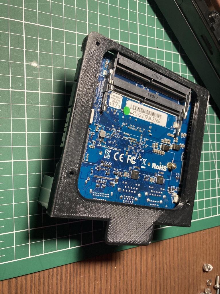
First up was the rails system. I started with a bracket holding the mainboard as can be seen below:
This bracket steers clear of all connectors, and has a ridge of 3mm on both sides which is used as a slide for the rail system. The rail system itself is mounted on brackets attached to the frame of the outer casing:
Electrical system
The following layout is used for the electrical system:
All wires should have proper connectors and bundled logically using a cable harness. With the side of the case opened, you should see as little cables as possible, to maintain a clean aestetic. This also means I would need a junction box to make all connections in the tree.
Parts and materials used
To build the system, the following major parts have been bought:
- 3 x Odroid H3 (with 2 x 16GB sodimm ddr4, 128GB eMMC, 512GB m2 nvme)
- Meanwell HRP-300-15 15V/300W psu
- Meanwell LRS-35-5 5V/35W psu
- Netgear GS305 gigabit switch
- Noctua NF-A12x25 5V PWM fan
- Noctua NF-A8 5V PWM fan
All chassis parts have been 3d printed in PETG, and are connected using either 3mm or 4mm nuts & bolts, or by using 8x2.5mm plastite screws. Design is done in Solidworks, and parts can be found here (TODO). All cabling has harnesses which are scavenged from old projects, and attached using heatshrink tubes, and has proper connectors (either U forks or a cable lug) so the copper is not damaged.
Part details
TODO


