LED banner wall
| NURDspace Project | |
|---|---|
| Participants | Bjornl |
| Skills | |
| Status | |
| Niche | |
| Purpose | |
| Tool | |
| Location | |
| Cost | |
| Tool category | |
{{{Name}}}Property "Tool Name" (as page type) with input value "{{{Name}}}" contains invalid characters or is incomplete and therefore can cause unexpected results during a query or annotation process. Property "Tool Image" (as page type) with input value "File:{{{Picture}}}" contains invalid characters or is incomplete and therefore can cause unexpected results during a query or annotation process. {{{Picture}}} {{#if:{{{Tool}}} | [[Tool Owner::{{{ProjectParticipants}}} | }} {{#if:{{{Tool}}} | [[Tool Cost::{{{Cost}}} | }}
Small sign
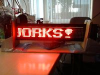
Yotson modified a small LED banner sign to be controlled by an Arduino. After hooking it up to the Dockstar and reprogramming SpaceBot it is now stored somewhere. Code is available on github, based on this earlier code.
15/12/13
Petraea dragged the sign out to give it a little dusting down to find that a bunch of columns no longer worked(See inset animation)
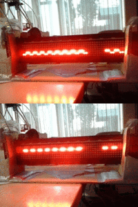 A little digging around identified that the CLK line was broken, so a simple extra wire was fitted to repair this.
Large sign
DeDaan brought in a larger sign. We plan on modifying this as well to have a second banner; if this is working, the smaller one will probably be used to indicate space state to the outside world from behind a window above the front door.
Current status
Software running on spacenanny in a screen unther the user nanny there is a window called bigledpanel if something goes wrong restart the script in that screen
cd ~/bigledpanel/server
while true; do python general.py -p /dev/ttyACM0 -s 9600 --mpdhost slab ; sleep 1 ; done
Source code
old
- First try https://gist.github.com/zarya/10f47d6b3097643f4016
- I starts to work https://gist.github.com/zarya/33fe46dac38b89f84d60
- last current code https://gist.github.com/zarya/24b3b56be5c432334539
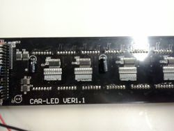
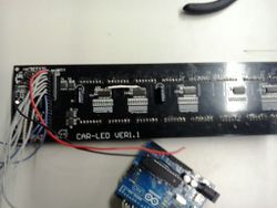
First images
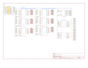
Schema's / Electronics
Arduino Pin setup
PORT_D
 0 (PD0) - UART RX
 1 (PD1) - D5
 2 (PD6) - D3 A0
 3 (PD5) - D4 A1
 4 (PD4) - D6 A2
 5 (PD3) - D2
 6 (PD2) - D0
 7 (PD1) - D1
PORT_B
 8  (PB0) - MR
 9  (PB1) - E1
 10 (PB3) - E2
PORT_C
 14 (A0,PC0) - A0
 15 (A1,PC1) - A1
 16 (A2,PC2) - A2
PIN OUT
01 - VCC
02 - VCC
03 - VCC
04 - SN74LS273N PIN 1 (MR)
05 - SN74LS138N PIN 5 (E2)
06 - SN74LS273N PIN 4 (D1)
07 - SN74LS138N PIN 1 (A0)
08 - SN74LS273N PIN 3 (D0)
09 - SN74LS138N PIN 2 (A1)
10 - SN74LS273N PIN 7 (D2)
11 - SN74LS138N PIN 3 (A2)
12 - SN74LS273N PIN 17 (D6)
13 - SN74LS138N PIN 4 (E1)
14 - SN74LS273N PIN 13 (D4)
15 - GND
16 - SN74LS273N PIN 8 (D3)
17 - GND
18 - SN74LS273N PIN 14 (D5)
19 - GND
20 - GND
Old info
The larger sign contains a separate control unit, programmed using a separate keyboard with a DB-9 like plug. It is attached to a PCB containing the LEDs with a 20 pin flatcable.
The control unit ( http://www.flickr.com/photos/bjornlammers/8425066292/in/photostream ) contains the following ICs:
- NEC D8049HC 195 (pre-programmed CPU)
- Motorola SN74LS373N ( http://www.alldatasheet.com/datasheet-pdf/pdf/5714/MOTOROLA/SN74LS373N.html )
- Toshiba TC5517APL (Static RAM, probably where the program is stored)
- unmarked IC, probably an EPROM
The Toshiba and the unmarked IC are in a socket, the other two are soldered to the PCB.
The LED panel ( http://www.flickr.com/photos/bjornlammers/8425075284/in/photostream ) contains:
- 6 * SN74LS273N ( http://www.alldatasheet.com/datasheet-pdf/pdf/5696/MOTOROLA/SN74LS273N.html )
- 6 * uA9668PC ( http://www.alldatasheet.com/datasheet-pdf/pdf/102338/FAIRCHILD/UA9668PC.html )
- 1 * SN74LS138N Decoder/demultiplexer ( http://www.alldatasheet.com/datasheet-pdf/pdf/5654/MOTOROLA/SN74LS138N.html )
- 2 * DM74LS259N 8-Bit Addressable Latches ( http://www.alldatasheet.com/datasheet-pdf/pdf/51060/FAIRCHILD/DM74LS259N.html )
- 4 * unmarked IC
See also this tech-archive thread: http://sci.tech-archive.net/Archive/sci.electronics.repair/2012-06/msg00302.html
