NurdNode
| NurdNode | |
|---|---|
| Participants | Cha0z97, User:petraea |
| Skills | Electronics, Programming |
| Status | Planning |
| Niche | Electronics |
| Purpose | Fun |
| Tool | No |
| Location | |
| Cost | |
| Tool category | |
NurdNode Property "Tool Image" (as page type) with input value "File:" contains invalid characters or is incomplete and therefore can cause unexpected results during a query or annotation process.
{{#if:No | [[Tool Owner::{{{ProjectParticipants}}} | }} {{#if:No | [[Tool Cost:: | }}
Description
The goal is to build wireless nodes that will control a bunch of LED's for cool lighting effects. The ultimate cool is to build enough, so we can put them in the connector pieces of our geodesic dome
Hardware design considerations
1 node will draw around 1A in current. For 31 nodes, this is obvisouly 31A in current at 5V, making the total power consumption 155W at full load. The current proposition is to bundle the power and signal lines into one cable, and run them in an upward spiraling fashion across each node, connecting them serially. The benefit of this setup is that it allows for easy addressing and it's simple. However, running 31A through a single power line requires a big, heavy and expensive cable.
The length of the power lines is determined at 60m. According to this site [1], at 3% acceptable loss, and using 5V at 31A the cable crossection is 16m2. A ballpark price estimate using Eijlander as supplier is roughly 330 euro.
An alternative would be to devide the power distribution into several groups. The upside is that we can get away with thinner cables, but we may require longer cables.
Yet another alternative is to raise the voltage of the grid to 12+V. This means we may use thinner power lines and still use the serial wiring setup. However, each node will have to be equipped with a switching power source to keep power dissipation at its lowest. This circuit will come at an extra cost, and having 31 nodes, this could escalate quickly.
(Why not elevate voltage a lot more, say 48V? Would reduce the current by an order of magnitude without adding more parts. Talloak (talk) 00:44, 4 May 2015 (CEST) )
Pinout of prototype
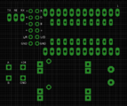
To connect the LED, hook up the wires to the corresponding channels. The + of the LED can be hooked up to either of the three + s. The design is a bit wonky, so that's why you get 3 + pins whereas only one is needed. The TX/RE/RX pins are used for debugging. Nothing is to be hooked up to those pins. The servo's need the lower 2x3 pins. I believe the diagram speaks for itself in this respect. Pin A and B are the DMX signal wires. Make sure all the A's are hooked up together as well as all the B's
Parts selection
IRL540 for power led stages?
TODO
Hardware
Calulate total length of cable required to connect all nodesCalculate price of power linesDesign power circuitDesign LED circuit (for optional leds)Design power stage for 3W ledSelect appropriate through-hole parts for breadboardingOrder thru-hole partsBuild thingamagic on breadboardSelect appropriate SMD parts for the final device.Select decoupling capsSelect connectors- Select N-channel MOSFET
- Select P-channel MOSFET
Design boardAssemble BOMDetermine pinout of PSUCreate pinout of prototype node- Build first prototype
- Test first prototype
- Build other prototypes
- Test out smaller FET as replacement for the fat bastards
- Fix design mistakes
- Finalise design
- Order PCB's
- Order metal framed stencil
- Create building instructions
- Equip 10 LEDs with wiring for prototyping purposes
- Build device that will zero in the Servo's
- Build device that tests a LED.
- Equip remaining 90 LED's with wiring
- Assemble 100 Pro mini's
- Assemble remaining 50 PSU's
- Assemble remaining 9 prototypes
- Assemble remaining 90 nodes
Cabling
- Determine guage of power cables
- Determine which signal wires to use
- Order more molex connectors
- Get wires at ijlander, or order
- Build cable
Total cable length based on 10M dome = 31 - 1 * 2m = 60m
Eijlander supples 16mm2 wire [2] for 334.80E for 120m (+ and -).
Ordering
100 pcs 3W Led100 pcs PSU100 Pro mini's200 Servos100 Lenses110 Jumper cables for soldering to LED3x solder pastePrototype StencilPrototype PCB'sEnough material for prototypes- Metal framed stencil for final design
- Final PCB's
- More molex connectors
- Enough materials for final nodes
Software
Create some spiffy code to make the blinkenlichten go blink blink.- Create a C&C lib that organises the nodes and takes care of the comms between the nodes and the higher level software. I'm thinking REST API for the higher level stuff and UDP multicast for the lower end. Suggestions welcome.
- Find a tool (better yet DIY) a tool that allows you to define an animation in 3D and project it on the geodome.
Links
- Potential 24V power supply: http://www.ebay.com/itm/321660472921
- Or 48V?: http://www.ebay.com/itm/261847060063
- Step down from 24V: http://www.ebay.com/itm/171381728637
- Leds: http://www.ebay.com/itm/191388798412
- Or: http://www.ebay.com/itm/221544924178 with added heatsinks onboard.
- Extra heatsinkery: http://www.ebay.com/itm/331286129263
- Sticky pads for connection: http://www.ebay.com/itm/121331880334
- Interesting source of servo's: http://www.giantshark.co.uk/product/167511/towerpro-sg90-9g-micro-servo - with returns in the UK. Promising!

