Collector
| Collector | |
|---|---|
| Participants | User:zmatt |
| Skills | |
| Status | |
| Niche | Electronics |
| Purpose | Industrial digital inputs |
| Tool | |
| Location | |
| Cost | |
| Tool category | General |
Collector-gpi-pic3.png {{#if:{{{Tool}}} | [[Tool Owner::{{{ProjectParticipants}}} | }} {{#if:{{{Tool}}} | [[Tool Cost::{{{Cost}}} | }}
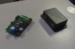
Two revisions of an industrial digital input module with LED indicators; first one seems to have 4 inputs and is probably a prototype, second version has 8 inputs and a proper enclosure. Two reed-switches were already in one of the connectors.
Supply voltage needs to be checked, probably 6V. In addition to a barrel jack they also have terminals for power to allow daisy-chaining.
Communication uses a proprietary but simple serial bus that can use standard phone cable, last device should have a terminator (is included, see photos). Bus address is configurable using DIP switches.
If anyone wants to play with these let me know, I may be able to look up the protocol.
To examine the second pcb, no unscrewing is required: Remove connectors. Remove the lid from the bottom (just pull) and pull out the two white tube-shaped spacers in the corners (may need pliers). You can then slide the pcb slightly and tilt it out.


