Measuring netfrequency
Jump to navigation
Jump to search
- arduino, on pin 3 a 1kHz clock signal
- the 1kHz clock signal is derived from a 10MHz OXCO via a PIC12F675 which divides it by 10k (see http://www.leapsecond.com/pic/src/pd04.asm by Tom van Baak)
- the signal to measure is connected to pin A0 of the arduino
- initially this is a sine wave from a rigol dg1022 (without external dso connected)
first attempt
- when an interrupt comes in via pin 3, a uS timestamp is taken ('t0')
- everytime the sign of the signal changes (via A0), then a timestamp is taken and the timestamp t0 is subtracted
- also pin 8 is inverted (output pin)
result
- it works somewhat but there's an enormous drift according to the arduino output (the timestamp difference goes all over the place)
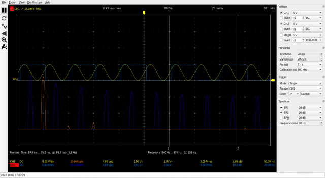
- the scope (hantek DSO-6022BL) says yellow is a fine 50Hz and blue 25Hz (as expected)
- strange!
- no, not strange: for measuring how long it takes for the sine to start moving up again, the micros() arduino call is used; this uses some way of measuring time that is not very accurate and thus the drift
- yellow is incoming 50Hz signal (CH1)
- blue is the toggle-pin (pin 8) (CH2)
when an ADC clock divider of 16 is taken, then the FFT of the pulses look(!) cleaner (when they distort...) than divider 32 or 128(not in the long run)
