Measuring netfrequency: Difference between revisions
Jump to navigation
Jump to search
(→result) |
No edit summary |
||
| Line 2: | Line 2: | ||
** the 1kHz clock signal is derived from a 10MHz OXCO via a PIC12F675 which divides it by 10k (see http://www.leapsecond.com/pic/src/pd04.asm by Tom van Baak) | ** the 1kHz clock signal is derived from a 10MHz OXCO via a PIC12F675 which divides it by 10k (see http://www.leapsecond.com/pic/src/pd04.asm by Tom van Baak) | ||
* the signal to measure is connected to pin A0 of the arduino | * the signal to measure is connected to pin A0 of the arduino | ||
** initially this is a sine wave from a rigol dg1022 (without external dso connected) | |||
Revision as of 15:10, 7 October 2022
- arduino, on pin 3 a 1kHz clock signal
- the 1kHz clock signal is derived from a 10MHz OXCO via a PIC12F675 which divides it by 10k (see http://www.leapsecond.com/pic/src/pd04.asm by Tom van Baak)
- the signal to measure is connected to pin A0 of the arduino
- initially this is a sine wave from a rigol dg1022 (without external dso connected)
first attempt
- when an interrupt comes in via pin 3, a uS timestamp is taken ('t0')
- everytime the sign of the signal changes (via A0), then a timestamp is taken and the timestamp t0 is subtracted
- also pin 8 is inverted (output pin)
result
- it works somewhat but there's an enormous lapse according to the arduino output (the timestamp difference goes all over the place)
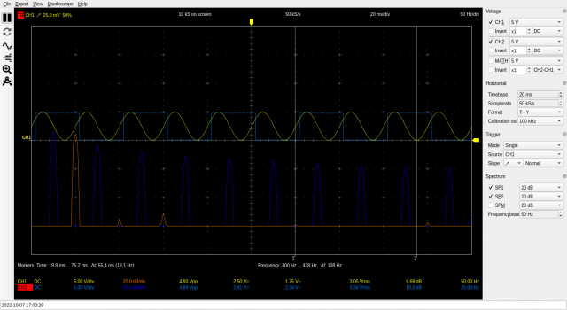
- the scope (hantek DSO-6022BL) says yellow is a fine 50Hz and blue 25Hz (as expected)
- strange!
- yellow is incoming 50Hz signal
- blue is the toggle-pin (pin 8)
