NrfSensorNode: Difference between revisions
| (24 intermediate revisions by 4 users not shown) | |||
| Line 1: | Line 1: | ||
{{Project | {{Project | ||
| | |Name=NrfSensorNode | ||
| | |Status=Active | ||
|Niche=Electronics | |||
|Picture=pro-mini-nrf-node.jpg | |||
|Tool=No | |||
}} | }} | ||
<gallery> | <gallery> | ||
Image:pro-mini-nrf-node.jpg | Image:pro-mini-nrf-node.jpg | ||
Image:pro-mini-nrf-node-ds18s20.jpg | Image:pro-mini-nrf-node-ds18s20.jpg | ||
Image:NrfSensorNode-PCB-V1-Front.jpg | |||
Image:NrfSensorNode-PCB-V1-Back.jpg | |||
</gallery> | </gallery> | ||
== Current situation @ space == | |||
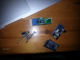
[[User:Zarya|Zarya]] had some PCBs made for Arduino Pro Mini based client nodes with an nrf24l01 radio for communications with the Raspberry Pi based masternode called [[SpaceNanny]]. Below the sotware [[User:Zarya|Zarya]] wrote for it: | |||
* https://github.com/zarya/NrfPiNode | |||
* https://github.com/zarya/NrfSensorNode | |||
* https://github.com/zarya/NrfUtils | |||
=== Spacenanny === | |||
[[SpaceNanny]] is the master node (node0) in the nrf network it takes care of transmitting the received sensor data to graphite (running on graphite.nurdspace.lan) the current code runs from a screen under the user nanny in the window called NRF this is how you restart it | |||
<pre> | |||
sudo bash | |||
cd /home/nanny/NrfPiNode | |||
while true ; do ./NrfPiNode ; sleep 1 ; done | |||
</pre> | |||
=== The arduino based nodes === | |||
* 1 Located near slab | |||
** Temperature | |||
** Pressure | |||
** Humidity | |||
* 2 Located near the front door (Only for relaying data from its child nodes) | |||
** 12 Doorbell node | |||
*** Listen for a doorbell press | |||
*** Temperature | |||
* 3 Skip button | |||
** Pulse contact for skipping the current track | |||
== NRF Sensor node == | == NRF Sensor node == | ||
| Line 13: | Line 43: | ||
== PCB == | == PCB == | ||
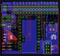
* The first batch of pcb's is in and is being used by some people. | |||
<gallery> | <gallery> | ||
File:Screenshot 2014-01-27 13.48.38.png | File:Screenshot 2014-01-27 13.48.38.png | ||
File:Screenshot 2014-02-21 10.18.42.png | |||
</gallery> | </gallery> | ||
=== Parts === | === Parts === | ||
| Line 28: | Line 56: | ||
* 3 x 15 pins male pin header | * 3 x 15 pins male pin header | ||
* 2 x 12 pins female header | * 2 x 12 pins female header | ||
* 2 x | * 2 x 4 pins female header | ||
* nrf24l01 radio | |||
* Arduino Pro Mini or clone (5V) | |||
== Low Power PCB == | == Low Power PCB == | ||
| Line 41: | Line 71: | ||
== Order == | == Order == | ||
=== PCB === | === PCB === | ||
* http://smart-prototyping.com/ | * We ordered at http://smart-prototyping.com/ | ||
** 10 x 7.23 euro | ** 10 x 7.23 euro | ||
** 50 x 25.61 euro | ** 50 x 25.61 euro | ||
| Line 57: | Line 87: | ||
* 10x http://www.ebay.com/itm/130702483183 (18 USD) | * 10x http://www.ebay.com/itm/130702483183 (18 USD) | ||
== | == Using the hardware with MySensors == | ||
In order to use the hardware with [https://www.mysensors.org/ MySensors], you need to change two pin numbers in MyConfig.h, which is located in your libraries directory. | |||
These are the right numbers: | |||
<pre> | |||
#define MY_RF24_CE_PIN 8 | |||
#define MY_RF24_CS_PIN 7 | |||
</pre> | |||
This needs to go '''before''': | |||
<pre> | |||
#include <MySensors.h> | |||
</pre> | |||
Latest revision as of 23:59, 26 May 2017
| NrfSensorNode | |
|---|---|
| Participants | Dennis |
| Skills | |
| Status | Active |
| Niche | Electronics |
| Purpose | |
| Tool | No |
| Location | |
| Cost | |
| Tool category | |
pro-mini-nrf-node.jpg {{#if:No | [[Tool Owner::{{{ProjectParticipants}}} | }} {{#if:No | [[Tool Cost::{{{Cost}}} | }}
Current situation @ space
Zarya had some PCBs made for Arduino Pro Mini based client nodes with an nrf24l01 radio for communications with the Raspberry Pi based masternode called SpaceNanny. Below the sotware Zarya wrote for it:
- https://github.com/zarya/NrfPiNode
- https://github.com/zarya/NrfSensorNode
- https://github.com/zarya/NrfUtils
Spacenanny
SpaceNanny is the master node (node0) in the nrf network it takes care of transmitting the received sensor data to graphite (running on graphite.nurdspace.lan) the current code runs from a screen under the user nanny in the window called NRF this is how you restart it
sudo bash
cd /home/nanny/NrfPiNode
while true ; do ./NrfPiNode ; sleep 1 ; done
The arduino based nodes
- 1 Located near slab
- Temperature
- Pressure
- Humidity
- 2 Located near the front door (Only for relaying data from its child nodes)
- 12 Doorbell node
- Listen for a doorbell press
- Temperature
- 12 Doorbell node
- 3 Skip button
- Pulse contact for skipping the current track
NRF Sensor node
PCB
- The first batch of pcb's is in and is being used by some people.
Parts
- R1 4.7k 1206 resistor (OneWire pullup)
- R2 4.7k 1206 resistor (DHT pullup)
- IC1 3.3v voltage regulator (AMS1117 AMS117-3.3 3.3V)
- C1,2 10uf Cap
- 3 x 15 pins male pin header
- 2 x 12 pins female header
- 2 x 4 pins female header
- nrf24l01 radio
- Arduino Pro Mini or clone (5V)
Low Power PCB
Wishlist
- Mostly SMD (to save space)
- Same as the standard board features.
- Battery monitor
- NRF Interrupt pin connectable (for feature use)
- add more
Order
PCB
- We ordered at http://smart-prototyping.com/
- 10 x 7.23 euro
- 50 x 25.61 euro
- zarya 10 x
- dreamer 5 x
- maze 10 x
- niz 5 x
- buzz 5x
Ebay part list
- 50 x 3.3v reg http://www.ebay.com/itm/300745587816 (3.40 USD)
- 10 x nrf24l01 http://www.ebay.com/itm/390678174596 (9.97 USD)
- 10 x http://www.ebay.com/itm/400389882462 (28.88 USD)
- 10x http://www.ebay.com/itm/130702483183 (18 USD)
Using the hardware with MySensors
In order to use the hardware with MySensors, you need to change two pin numbers in MyConfig.h, which is located in your libraries directory. These are the right numbers:
#define MY_RF24_CE_PIN 8
#define MY_RF24_CS_PIN 7
This needs to go before:
#include <MySensors.h>


