Li-Ion battery capacity meter: Difference between revisions
No edit summary |
No edit summary |
||
| (5 intermediate revisions by the same user not shown) | |||
| Line 20: | Line 20: | ||
Controller: | Controller: | ||
Choosing the Arduino Pro Mini for this project, because it is small, cheap and easy to use, and I have several in my partsbin that need using. | Choosing the Arduino Pro Mini for this project, because it is small, cheap and easy to use, and I have several in my partsbin that need using. | ||
Note on timing: | |||
So the Arduino Pro Mini has a ceramic resonator instead of a crystal, how about [http://forum.arduino.cc/index.php?topic=13289.0 timing accuracy] ? | |||
The accuracy of the millis() function is governed by the clock in your Arduino board which is driven by either a crystal or ceramic resonator. A crystal has an accuracy of roughly +/- 50 parts per million (ppm) or so (some are more accurate some are less, but 50ppm is about right for a cheap crystal). | |||
50 ppm = 0.005% accuracy which in your case equals about 0.72 seconds deviation from the nominal delay over 4 hours at 16MHz | |||
A ceramic resonator is about 0.5% accurate = 72 seconds over 4 hours or about 1 minute 12 seconds at 16MHz. | |||
Both these time errors are very much greater than the accuracy of the millis() function so it's accuracy can effectively be ignored. | |||
(in short, good enough for this application) | |||
Power supply: | Power supply: | ||
analogRead( | analogRead(INTERNAL) should do the trick as reference to get a stable voltage reading. | ||
If not a calibrated external power supply may need to be added to the project. | If not a calibrated external power supply may need to be added to the project. ([http://www.skillbank.co.uk/arduino/measure.htm Precise voltage measurement with the Arduino board]) ([http://rlogiacco.wordpress.com/2015/03/04/arduino-analogread-pitfalls/ Arduino analogRead pitfalls]) | ||
FET: | FET: | ||
Using Dave Jones (EEVBlog) DC constant current load as reference, I have selected the IRL540 logic level FET. | Using Dave Jones (EEVBlog) [http://youtu.be/8xX2SVcItOA DC constant current load] as reference, I have selected the IRL540 logic level FET. | ||
The advantage of this FET is that at 5V the Gate will be completely driven open, whereas normal FET's require higher gate voltages to be driven open completely. I could have chosen other ones but this one seems easily available and the specifications meet my requirements. | The advantage of this FET is that at 5V the Gate will be completely driven open, whereas normal FET's require higher gate voltages to be driven open completely. I could have chosen other ones but this one seems easily available and the specifications meet my requirements. | ||
Resistor: | Resistor: | ||
Given that the max power the resistor will dissipate is 2.1 Watt (4.2 Volt at 500mA discharge current) 10 10Ω 1 | Given that the max power the resistor will dissipate is 2.1 Watt (4.2 Volt at 500mA discharge current) 10 10Ω 0.5W 1% resistors should do the trick which make up a 1Ω 5W resistor. There is enough overhead might a discharge of 1A be chosen later which will be 4.2W tops. | ||
Using a relay for switching the load on and off. Could have used a high level switching FET but a relay is easier and has less resistance, and less hassle. | Using a relay for switching the load on and off. Could have used a high level switching FET but a relay is easier and has less resistance, and less hassle. | ||
Latest revision as of 01:10, 28 February 2017
| Li-Ion (18650) battery capacity meter | |
|---|---|
| Participants | Danieltoo |
| Skills | 1337 Skillz, Arduino, Coding, Hackery |
| Status | Planning |
| Niche | Hardware |
| Purpose | Infra |
| Tool | No |
| Location | |
| Cost | |
| Tool category | Electronics |
Li-Ion (18650) battery capacity meter
Heapof18650cellsnew.png {{#if:No | [[Tool Owner::{{{ProjectParticipants}}} | }} {{#if:No | [[Tool Cost::{{{Cost}}} | }}
As of many hackerspaces we rescue 18650 cells from old laptop batteries and other sources
We do have a charger but no good way of testing the capacity of each cell before it goes into the parts pile
Making a capacity tester would solve this. One could buy a chinese unit from fleabay but where is the fun in that? :)
Component considerations:
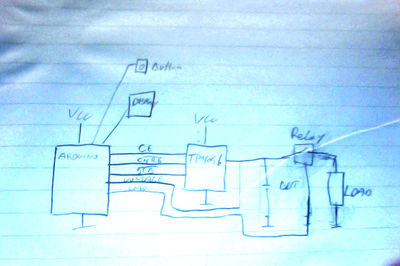
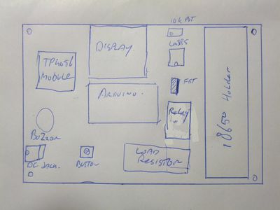
Controller: Choosing the Arduino Pro Mini for this project, because it is small, cheap and easy to use, and I have several in my partsbin that need using.
Note on timing: So the Arduino Pro Mini has a ceramic resonator instead of a crystal, how about timing accuracy ? The accuracy of the millis() function is governed by the clock in your Arduino board which is driven by either a crystal or ceramic resonator. A crystal has an accuracy of roughly +/- 50 parts per million (ppm) or so (some are more accurate some are less, but 50ppm is about right for a cheap crystal). 50 ppm = 0.005% accuracy which in your case equals about 0.72 seconds deviation from the nominal delay over 4 hours at 16MHz A ceramic resonator is about 0.5% accurate = 72 seconds over 4 hours or about 1 minute 12 seconds at 16MHz. Both these time errors are very much greater than the accuracy of the millis() function so it's accuracy can effectively be ignored. (in short, good enough for this application)
Power supply: analogRead(INTERNAL) should do the trick as reference to get a stable voltage reading. If not a calibrated external power supply may need to be added to the project. (Precise voltage measurement with the Arduino board) (Arduino analogRead pitfalls)
FET: Using Dave Jones (EEVBlog) DC constant current load as reference, I have selected the IRL540 logic level FET. The advantage of this FET is that at 5V the Gate will be completely driven open, whereas normal FET's require higher gate voltages to be driven open completely. I could have chosen other ones but this one seems easily available and the specifications meet my requirements.
Resistor: Given that the max power the resistor will dissipate is 2.1 Watt (4.2 Volt at 500mA discharge current) 10 10Ω 0.5W 1% resistors should do the trick which make up a 1Ω 5W resistor. There is enough overhead might a discharge of 1A be chosen later which will be 4.2W tops.
Using a relay for switching the load on and off. Could have used a high level switching FET but a relay is easier and has less resistance, and less hassle.
partlist:
- Arduino pro mini
- Display
- Button
- TP4056 module
- 18650 battery holder
- 5v relay
- DC current load
  \
   - Logic level N chan mosfet
   - lm385 opamp
   - 50k 10 turn pot
   - 1 Ohm 5 Watt resistorrrr


